
Cause and Effect Matrices
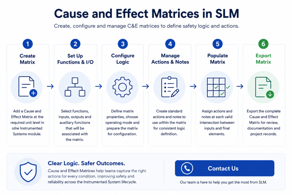
Cause and Effect Matrices provide a structured way to define how process inputs should trigger alarms, shutdowns and other protective actions within an Instrumented System.
In the SLM Instrumented Systems module, users can create and manage a Cause and Effect Matrix, associate it with selected functions and instruments, populate the required logic, and export the completed matrix for review or documentation.
This guide explains how to create a matrix at the correct unit level, configure its properties, select the relevant functions and I/O, and prepare the matrix for population with actions and notes.
What Are Cause and Effect Matrices?
A Cause and Effect Matrix is an engineering document that shows the relationship between defined causes and the actions that should occur in response. Causes are typically represented by process inputs or initiating conditions, while effects may include alarms, trips, shutdowns or changes to final elements.
Within SLM, the matrix is built using information already stored against Instrumented System functions, input objects, output objects and related auxiliary functions. This allows users to manage the logic in a structured format rather than recreating the same engineering data in a separate document.
The completed matrix helps teams understand which protective actions are associated with each input condition and provides a clear record of the intended Instrumented System behaviour.
Creating Cause and Effect Matrices in SLM
To create a Cause and Effect Matrix in SLM, navigate to the Instrumented Systems module and select the unit where the matrix should reside. From the unit level, open the Edit Tools menu and select the option to add a Cause and Effect Matrix.
The matrix should be created beneath the unit that contains the functions and instruments it will manage. This is important because the available functions are determined by the matrix’s position within the SLM object tree.
During creation, users enter the Cause and Effect Matrix ID and can select Save and Edit to move directly into the newly created object. The matrix then appears beneath the selected unit in the object tree.
Before creating the matrix, confirm that the correct process unit has been selected and that the required Instrumented System objects have already been created. For a broader explanation of how these objects are organised, see the Instrumented Systems Overview.
Setting Up Functions and Instruments
After the Cause and Effect Matrix has been created, the next step is to configure its properties and select the functions and instruments that will form part of the matrix.
From the Setup tab, users can edit properties such as the matrix name, description and revision. They can then use the function and I/O management controls to associate the required Instrumented System functions with the matrix.
SLM presents the functions available at the same unit level as the matrix. Each function can be reviewed using information such as its function type, ID and description before it is selected.
Once the functions have been chosen, users can select the associated inputs and outputs. These may be selected individually or added together. Where a selected function has related auxiliary functions, those can also be included.
After saving the selections, the Setup tab displays the functions, inputs, outputs and auxiliary functions associated with the matrix. The selection process can be reopened later when functions or instruments need to be added, changed or removed.
Because the matrix automatically uses information stored against these objects, the relevant function and instrument records should be completed before the matrix is populated. For more detail on the underlying safety functions, see Instrumented Functions (IPLs).
Configuring Cause and Effect Logic
Once the functions and associated instruments have been selected, users can begin configuring how the Cause and Effect Matrix will operate. The matrix automatically displays information retrieved from the selected Instrumented System functions, inputs and final elements, providing a structured foundation for defining safety logic.
The Cause and Effect Matrix tab displays the selected functions and instruments in a grid format. Users can choose how many functions will appear within the matrix and specify the applicable operating mode, such as normal operation, start-up or shutdown.
Alongside the matrix grid, SLM provides dedicated areas for Cause and Effect Notes and Cause and Effect Actions. These are used to define the logic that will later be assigned to each valid intersection between an initiating input and its corresponding protective action.
Because only valid relationships can be configured, the matrix helps maintain consistency while reducing the likelihood of incorrect logic being introduced into the safety design.
If the associated functions or instruments change during the project lifecycle, users can return to the Setup tab to update the selections before continuing with matrix configuration. This ensures the Cause and Effect Matrix remains aligned with the latest Instrumented System design. For guidance on configuring complete safety systems, see Configuring a Safety Instrumented Function.
Managing Actions and Notes
Cause and Effect Actions and Notes provide the information used to define how each protective function should respond when a particular condition occurs. Rather than entering free text into every matrix cell, users select predefined actions and notes that can be reused throughout the matrix.
Notes are created by selecting Add C&E Note, entering a description and saving the record. SLM automatically assigns each note a reference number, allowing it to be referenced consistently wherever required within the matrix.
Actions are managed separately from the matrix itself and represent the responses available to engineering teams. Examples include alarm generation, de-energising equipment or other predefined protective actions that comply with company engineering standards.
Using standardised actions and notes improves consistency across multiple Cause and Effect Matrices while making the completed documentation easier for operators, maintenance personnel and reviewers to understand.
Where organisational standards evolve, authorised users can update the available Cause and Effect Actions within the System module, ensuring future matrices continue to use approved terminology and operating practices.
Populating the Cause and Effect Matrix
After the setup is complete, the Cause and Effect Matrix can be populated by selecting the appropriate intersection between an initiating input and the required final element. Each populated cell represents the logic that should occur when that specific condition is detected.
For every valid intersection, users choose a predefined Cause and Effect Action together with any supporting Cause and Effect Notes. Once saved, these selections become part of the engineering logic displayed within the matrix.
As additional actions and notes are assigned, the matrix develops into a complete representation of the Instrumented System’s protective behaviour. This provides a clear visual reference for engineers responsible for reviewing, validating and maintaining the safety logic.
Before completing the matrix, verify that all required functions, inputs, outputs and auxiliary functions have been associated correctly and that the approved organisational actions and notes have been selected throughout.
A well-maintained Cause and Effect Matrix supports design reviews, commissioning activities and ongoing lifecycle management by providing a single, structured view of cause-and-effect relationships across the Instrumented System.
Exporting Cause and Effect Matrices
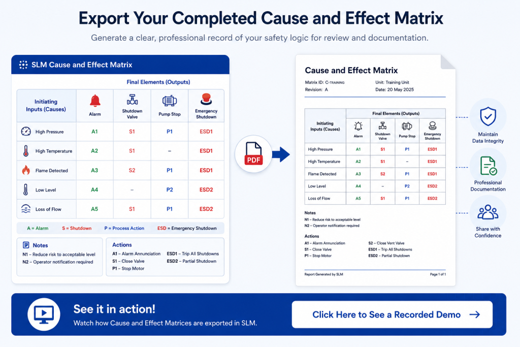
Once the Cause and Effect Matrix has been completed, SLM allows users to export the matrix into a physical document for distribution, review or project documentation. The exported version maintains the same layout as the matrix displayed within SLM, ensuring the information remains easy to interpret outside the application.
To export the matrix, select the required Cause and Effect Matrix from the object tree, open the Cause and Effect Matrix tab and choose the Export option. Users can then specify a location for the exported file before opening the completed document.
The exported matrix includes the configured relationships between causes and effects together with any associated notes that have been added during the engineering process. This provides a convenient record for design reviews, commissioning activities and ongoing lifecycle documentation.
Maintaining an up-to-date exported copy also supports communication between engineering, operations and maintenance teams, ensuring everyone is working from the same approved Cause and Effect Matrix.
For organisations maintaining formal functional safety documentation, exported matrices can be used alongside other engineering records to demonstrate how protective actions have been defined throughout the Instrumented System lifecycle.
Best Practices for Cause and Effect Matrices
A well-structured Cause and Effect Matrix improves consistency across Instrumented System projects while making safety logic easier to review, maintain and verify. Establishing standard engineering practices helps reduce errors and simplifies future modifications.
- Create the matrix only after the required functions and instrument objects have been completed.
- Verify that all relevant inputs, outputs and auxiliary functions have been associated before populating the matrix.
- Use standardised Cause and Effect Actions and Notes to maintain consistency across projects.
- Review populated matrix intersections carefully to confirm the intended protective response.
- Export the completed matrix as part of the project documentation and change management process.
Following a consistent workflow helps ensure Cause and Effect Matrices remain accurate throughout the lifecycle of the Instrumented System and continue to support engineering reviews, audits and future system modifications.
Learn More About Instrumented Systems
Cause and Effect Matrices form one part of a complete Instrumented System engineering workflow. Additional guides within the Instrumented Systems documentation explain how safety functions are configured, managed and documented throughout the lifecycle.
- Instrumented Systems Overview
- Configuring a Safety Instrumented Function
- Instrumented Functions (IPLs)
- Safety Requirement Specification (SRS)
- SIL Calculation Reports
For further guidance on functional safety lifecycle requirements and Safety Instrumented Systems, see the International Electrotechnical Commission (IEC), which publishes the IEC 61511 standard used throughout the process industries.
Cause and Effect Matrices
0:06
Welcome to this Application Explainer video, part of our SLM Instrumented Systems topic range.
0:12
In this video, we’ll be covering the subject of cause and effect matrices within SLM.
0:19
Within the SLM Instrumented Systems module, users can create and manage cause and effect matrices to specify logic and actions for the Instrumented Systems functions.
0:31
The following information will be covered in this training.
0:34
Chapter one will be creation of cause and effect matricy objects, Chapter 2 will be the setup of the cause and effects matrix, Chapter 3 will be Actions and notes.
0:46
Chapter 4 will be populating the cause and effect matrix, Chapter 5 will be configuring the cause and effect actions and Chapter 6 will be exporting the cause and effect matrix.
1:03
In Chapter 1 we’ll be covering how to add the cause and effect matrix object and things to consider where the cause and effect matrix will reside within the SLM system.
1:16
To create an SLM Cause and Effects matrix, the user will have to come to Instruments and Systems module, come across the object tree and click on the Units level.
1:29
From here they can go to the Edit Tools, drop down and click on Add Cause and Effects matrix.
1:43
We then have this Add Cause and Effects Matrix popup window where we can add the cause and effect ID.
1:56
We’ll use C training.
1:58
We will then use this Save and Edit button to navigate directly to the new cause and Effect matrix.
2:06
We’ll also note that the Cause and effect matrix has been created in the object tree underneath the desired unit.
2:17
Chapter 2.
2:18
In this chapter we will cover the Cause and Effects matrix properties, the association of functions and instruments within the Cause and Effects matrix, and things to consider.
2:29
The Cause and Effects matrix will auto populate with data filled in on the SLM functions and instrument objects.
2:36
Have you completed filling in the data fields on these objects?
2:42
Once the Cause and Effect matrix objects has been created, it’s now time to run through the setup.
2:48
So if we come to the Setup tab, we can see here that we can edit the Cause and Effects matrix properties.
2:55
Properties such as name, description, and revision, or the user can start by clicking on the Manage functions and selected iOS button that are going to be associated with this risk matrix.
3:10
Here we will see a list of functions that are available for selection.
3:14
These are the functions that exist at the same level and unit as the cause and effects matrix we’ve created.
3:21
We can see that we have the function type, the function ID, and the function description.
3:27
By selecting these, we’re saying that these will be associated with our cause and effects matrix.
3:33
If I now click next, this is showing us a list of the inputs and output that are again associated with the functions that were selected in the previous step.
3:44
I can individually select them, or you can associate all of them by clicking the square at the top.
3:52
Additionally, if any of the functions in the previous step had any related auxiliary functions, we can also associate these with our cause and effects matrix.
4:11
Once we have made all our selections and we’re satisfied, I’ll just select them all.
4:16
We can hit Save and now on the Setup tab we can see a list of the functions, the selected inputs, the selected outputs, and the selected auxiliary functions that are associated with our cause and effects matrix.
4:32
If we ever need to change, remove, or add any new functions or instrumentations, we can simply click on the Manage Functions and selected iOS button again and go through this process again.
4:50
In Chapter 3, we’ll cover the view of the Cause and effect actions and the creation of Cause and Effects notes.
4:59
Once we have finished selecting the functions and the instruments that will be associated with this Cause and Effects matrix, we can come across to the Cause and Effects Matrix tab.
5:09
If we Scroll down, you’ll notice that the functions and instruments that we chose during the setup phase will have information that has previously been populated on these objects.
5:24
This is automatically pulled into the C&E matrix for these functions, the inputs, and for the final elements.
5:41
If we scroll to the top left corner of the C&E matrix, we’ll be able to choose how many of the functions that we selected previously will be part of the cause and effects matrix grid.
5:55
And we also have the option to select whether the operation mode is normal, shut down, or start up.
6:03
In this space.
6:04
Just below we have the cause and effect matrix notes, and to the right of that we have the cause and effect actions.
6:11
These will be used to populate the logic at the intersections for the inputs and the final elements on this actual C&E matrix.
6:20
It’s only available where these intersection points are related.
6:28
In Chapter 4, we’ll cover how to populate the actions and notes for the cause and effects matrix, and things to consider.
6:36
Are all the necessary notes created prior to populating the cause and effects matrix.
6:41
Are the actions listed correctly for the Organizational standards for the C&E matrix notes in the top left hand corner, if we click Add C&E note, we can add a note description, just call it Note 1.
6:57
Then we click Save, we can see reference number is automatically assigned.
7:02
So let’s just add another note and we’ll just call it Note two Save changes.
7:11
The C&E actions are listed just to the right hand side of the notes and for the actual population of the C&E matrix at the intersections, we can simply click on the intersection of the input and output and make a selection from our list of actions and our list of notes here.
7:32
So de energize note one click save and we can see that the intersection is populated with de energize and note one.
7:43
On the next intersection, we go for alarm and Note 2 and save.
7:51
Now the C&E matrix is beginning to be populated in these intersections with the correct notes and actions.
8:01
In Chapter 5, we’ll cover configuring the cause and effects actions within the SLM Systems module and things to consider.
8:09
Does your user account have privileges to make these kind of changes to change or alter the C&E actions?
8:18
The user, if they have the correct privileges, can come to this.
8:22
Drop down and select the System module.
8:29
Search this system menu for C&E.
8:34
Hit Return.
8:36
The dropdown we’re after is the Cause and Effects effect actions, and in here we can edit existing actions, we can delete them, or we could add new ones with the Add Options button.
8:52
In Chapter 6, we’re going to cover how to export the Cause and Effects matrix if needed, in physical file format.
8:59
Once the See Any matrix is complete in SLM, if the end user needs a physical exported document, we can click on the Cause and Effects matrix in the object tree here, click on the Cause and Effects Matrix tab at the top, hit the Export button.
9:18
We can then choose an export location.
9:21
From there, we can open the export.
9:24
As you can see, we have the full C&E matrix document in exactly the same layout as it is in SLM, including the notes that we added.


