Instrumented Systems Overview
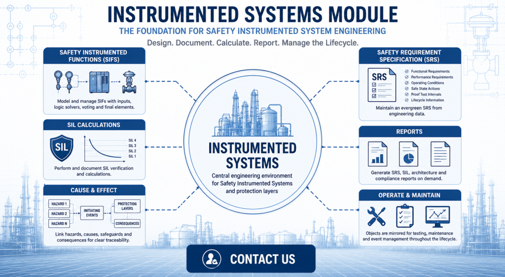
Instrumented Systems provide the framework for designing, documenting and maintaining Safety Instrumented Systems (SIS) throughout their lifecycle. Within the SLM platform, the Instrumented Systems module enables engineers to model Safety Instrumented Functions (SIFs), document Safety Requirement Specifications (SRS), perform SIL calculations and maintain a complete engineering record from design through operation.
Rather than managing safety information across multiple disconnected spreadsheets and documents, Instrumented Systems bring engineering data together into a single controlled environment. This improves traceability, supports functional safety compliance and provides an auditable record of every configured protection layer.
This guide introduces the Instrumented Systems module, explains how its object hierarchy is structured and shows how SLM supports engineering teams with integrated documentation, reporting and lifecycle management.
What Is the Instrumented Systems Module?
The Instrumented Systems module is the central engineering environment within SLM for designing and managing Safety Instrumented Systems. It provides a structured object model that represents the protection layers installed within a process plant while maintaining the engineering data required throughout the functional safety lifecycle.
Each configured object stores its own engineering information, allowing documentation, calculations and reports to remain connected to the physical safety function rather than existing as isolated documents.
Typical activities supported within the module include:
- Creating Safety Instrumented Functions (SIFs).
- Managing Independent Protection Layers (IPLs).
- Recording Safety Requirement Specifications (SRS).
- Maintaining engineering documentation.
- Producing SIL calculation reports.
- Generating SRS reports.
- Supporting verification and lifecycle audits.
- Providing a controlled source of engineering data.
Because all engineering information is stored within a structured database, organisations can maintain an evergreen record of their Safety Instrumented Systems rather than relying on static documents that quickly become outdated.
For more detail on documenting lifecycle requirements, see the Safety Requirement Specification (SRS) guide.
What Can Be Managed in Instrumented Systems?
The Instrumented Systems module is designed to manage far more than individual Safety Instrumented Functions. At the unit level, engineers can configure multiple types of protection systems and associated engineering objects, providing a complete representation of the plant’s protection architecture.
Supported objects can include:
- Safety Instrumented Functions (SIFs).
- High Integrity Protection Systems (HIPS).
- Interlocks.
- Fire and Gas functions.
- Basic Process Control Systems (BPCS).
- Cause and Effect Matrices.
- Equipment records.
- Alarms.
- Control and instrumentation functions.
Additional objects can be created directly from the unit level using the module’s editing tools, allowing organisations to configure their engineering model to reflect the actual plant design.
Maintaining all protection layers within a single engineering structure improves visibility across the process while reducing duplicated documentation and improving consistency between projects.
Many organisations also use the module to provide a single location for engineering reviews, project documentation and lifecycle reporting.
For organisations implementing complete Safety Instrumented Systems, the Safety Systems software solution provides an integrated platform for managing these engineering activities.
Understanding SIF Voting Structures
One of the key capabilities of the Instrumented Systems module is its ability to represent the logical structure of a Safety Instrumented Function. Rather than documenting only the finished SIF, SLM models the complete hierarchy of objects that make up the protection function.
A typical Safety Instrumented Function contains:
- Input Groups.
- Input Voting Groups.
- Individual Inputs.
- Voting Setpoints.
- Logic Solvers.
- Output Groups.
- Output Voting Groups.
- Final Outputs.
This hierarchy mirrors the way many real Safety Instrumented Systems are engineered and allows each component to store its own engineering information while remaining connected to the complete protection function.
Voting structures define how multiple inputs are evaluated before initiating a protective action. By modelling these structures directly within the engineering database, organisations gain improved traceability between the documented design and the implemented safety logic.
As engineers navigate through the object tree, selecting any object displays its associated engineering template, making it straightforward to review, update and maintain lifecycle information for every part of the Safety Instrumented Function.
The Safety Instrumented Function (SIF) guide explains the role these functions play within the wider functional safety lifecycle.
Inputs, Logic Solvers and Outputs
Every Safety Instrumented Function is built from three fundamental elements: inputs, a logic solver and outputs. Together, these components detect hazardous conditions, determine whether protective action is required and place the process into a safe state.
Within the Instrumented Systems module, each of these elements is represented as an individual object within the engineering hierarchy. Selecting an object displays its associated data entry template, allowing engineers to maintain the information required throughout the safety lifecycle.
The module supports documentation for:
- Input devices and setpoints.
- Input voting groups.
- Logic solvers.
- Output groups.
- Output voting groups.
- Final elements.
Capturing information at each level improves traceability and ensures every part of the Safety Instrumented Function contributes to a complete engineering record.
For more information on configuring complete protection functions, see the
For more information on configuring complete protection functions, see the Configuring a Safety Instrumented Function guide.
Managing Instrumented System Data
Each object within the Instrumented Systems module includes dedicated data entry tabs that store engineering information throughout the lifecycle of the Safety Instrumented System.
Rather than maintaining multiple disconnected documents, engineers can record functional requirements, calculations and supporting information directly against the relevant engineering object.
Benefits of this structured approach include:
- Consistent engineering documentation.
- Improved traceability.
- Reduced duplication of information.
- Simplified engineering reviews.
- Improved audit readiness.
- Controlled lifecycle records.
Because every object stores its own engineering information, teams can quickly review and update documentation whenever modifications are made to the Safety Instrumented System.
Creating an Evergreen Safety Requirement Specification
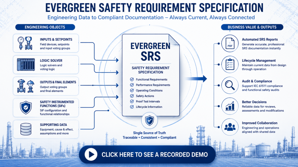
One of the key advantages of the Instrumented Systems module is its ability to maintain an evergreen Safety Requirement Specification (SRS). Instead of relying on static documents that require manual updates, SLM generates SRS information directly from the engineering data stored throughout the object hierarchy.
Information entered across the various engineering templates is automatically brought together within the SLM Design SRS tab, creating a single, consistent source of lifecycle documentation.
This provides several important benefits:
- Improves consistency across engineering teams.
- Reduces duplicated documentation.
- Keeps SRS information synchronised with engineering changes.
- Supports engineering reviews and Functional Safety Assessments.
- Simplifies report generation.
Maintaining an evergreen SRS helps ensure that engineering documentation remains aligned with the implemented system throughout design, operation and future modifications.
For a detailed explanation of this process, see the Safety Requirement Specification (SRS) guide.
Printing and Reporting Safety Requirement Specifications
Once engineering data has been completed, SLM allows users to generate professional Safety Requirement Specification (SRS) reports directly from the Instrumented Systems module. Reports are created using the engineering information already stored within the object hierarchy, eliminating the need to manually compile documentation.
Users can generate reports directly from an individual Safety Instrumented Function or by selecting a wider scope within the reporting tools. Generated reports provide a consistent format for engineering reviews, project documentation and lifecycle records.
Common reporting activities include:
- Printing individual SRS reports.
- Generating reports for multiple Safety Instrumented Functions.
- Supporting engineering design reviews.
- Providing controlled project documentation.
- Maintaining lifecycle audit records.
Because reports are generated directly from the engineering database, they remain aligned with the latest approved engineering information.
For a detailed explanation of SRS documentation and reporting, see the Safety Requirement Specification (SRS) guide.
Connecting Instrumented Systems with Operate and Maintain
The Instrumented Systems module is closely integrated with the Operate and Maintain module. Engineering objects created during system design are automatically mirrored, allowing operational teams to manage testing, maintenance and event records without recreating equipment information.
This integration provides continuity throughout the safety lifecycle by linking engineering design with ongoing operational activities.
Examples include:
- Proof testing.
- Maintenance records.
- Inspection activities.
- Event history.
- Equipment lifecycle management.
Maintaining a shared data model reduces duplicated effort while helping engineering and maintenance teams work from the same controlled source of information.
Benefits of an Integrated Instrumented Systems Workflow
Managing Safety Instrumented Systems within a single engineering platform provides greater consistency than maintaining separate spreadsheets, reports and standalone documents.
By connecting engineering data, Safety Requirement Specifications, SIL calculations and lifecycle reporting, organisations can improve documentation quality while simplifying future modifications and audits.
Key benefits include:
- Centralised engineering records.
- Improved traceability.
- Evergreen Safety Requirement Specifications.
- Integrated reporting.
- Support for IEC 61511 lifecycle activities.
- Reduced manual documentation effort.
- Improved collaboration between engineering disciplines.
For organisations implementing functional safety programmes across multiple facilities, an integrated engineering workflow helps ensure consistent documentation and more efficient lifecycle management.
The IEC 61511 standard defines the lifecycle requirements for Safety Instrumented Systems used in the process industry, making well-managed engineering documentation an important part of demonstrating compliance.
Explore the Instrumented Systems Guides
The Instrumented Systems module includes a range of tools for designing, documenting and maintaining Safety Instrumented Systems throughout their lifecycle.
Continue exploring the Instrumented Systems knowledge base:
- Safety Requirement Specification (SRS) – document and manage lifecycle requirements for Safety Instrumented Functions.
- SIL Calculation Reports – generate and review SIL verification reports.
- Configuring a Safety Instrumented System – build complete Safety Instrumented Systems within SLM.
- Safety Instrumented Function (SIF) – understand how SIFs reduce process risk.
- Safety Systems Software – discover the complete MSS Safety Systems solution.
Instrumented Systems Overview
0:06
Welcome to this Application Explainer video, part of our Instrumented Systems topic range.
0:11
In this video, we’ll cover an overview of the Instrumented Systems module.
0:15
The Instrumented Systems module is where SLM users can design their safety instrumented systems and associated independent protection layer structures.
0:26
Maintaining data in the Instrumented Systems module provides the user with a complete, accurate and up to date safety requirement specification available on demand.
0:36
The Instrumented Systems module also serves as an auditable trail that can be used for independent verification of sys data and structures.
0:45
If we come to the Instrumented Systems module and select A unit, we can see a display in the object tree of the objects that are available at the unit level.
0:53
They consist of alarms, BPCSS, cause and effect matrices, equipment, fire and gas functions, HIPS, interlocks, CIFS, and CIS’s.
1:02
These objects can be manually added to the object tree at the unit level by using the Edit Tools drop down in the Unit view template area.
1:10
So if we select Edit Tools, we can see a list of all the objects that can be added to the unit level Safety instrumented systems.
1:18
If we expand the tree is comprised of fire and gas functions, HIPS, interlocks, and safety instrumented functions.
1:28
These objects contain voting structures which are visible in the object tree.
1:32
A voting structure describes the programming logic of the SYS Sifs.
1:38
HIPS and interlocks consist of logic solvers, input groups, and output groups.
1:44
So if we expand this first SIF, we can see we have an input group.
1:52
If we expand into there, we have the input voting group, and inside here we have a list of inputs which if we drill down on an input, can also have setpoints.
2:04
We also have voting set points underneath the input voting group.
2:08
If we select any of these objects or voting groups, we can see their data entry template here on the right hand side.
2:14
If we close the input group and look at the logic solvers, we can see we have a logic solver in here.
2:20
And if we expand the output groups, we have an output voting group and inside there we have outputs.
2:28
Again by clicking on the output.
2:30
You can see the data entry template here on the right hand side.
2:33
Data entry tabs are found at the Alarm Interlock, BPCS, SIF, HIPS and SIF objects.
2:40
So if we select this SIF we can see a list of the data entry tabs at the top.
2:44
So we have an overview, we have a general tab calculations, and if we scroll to the far right, all the information from the data entry tabs are aggregated in the SLM Design SRS tab.
2:57
This tab provides an Evergreen single source of SRS data and reports.
3:02
To print out an SRS report, we select the tab, we come over to the left to the print button and select it.
3:09
We then choose our download location and click Save, and now we have a PDF report of our SRS.
3:25
It’s worth noting that objects created in the Instrumented Systems module such as alarms, BPCSS, Interlocks, sys, sys, logic, solvers, inputs, outputs, they’re all automatically mirrored in the Operate and Maintain module where the user can manage the record testing and event data.


