Mangan Software Solutions Achieves TÜV Certification for SLM™ Safety Lifecycle Manager v2.5

[Houston, October 10, 2023] — Mangan Software Solutions, a leading provider of safety and risk management software solutions, is proud to announce that its Safety Lifecycle Manager (SLM™ v2.5) software has received TÜV re-certification for compliance with the International Electrotechnical Commission (IEC) 61511 standard. This certification represents a significant milestone in Mangan’s commitment to delivering industry-leading solutions that enhance safety and reliability in process industries. 

 IEC 61511 is a globally recognized standard for the functional safety of safety instrumented systems (SIS) in the process industry. It provides a framework for managing the entire safety lifecycle, from concept to decommissioning, and is crucial for ensuring the safety of critical processes in sectors such as chemical, oil and gas, and manufacturing. 

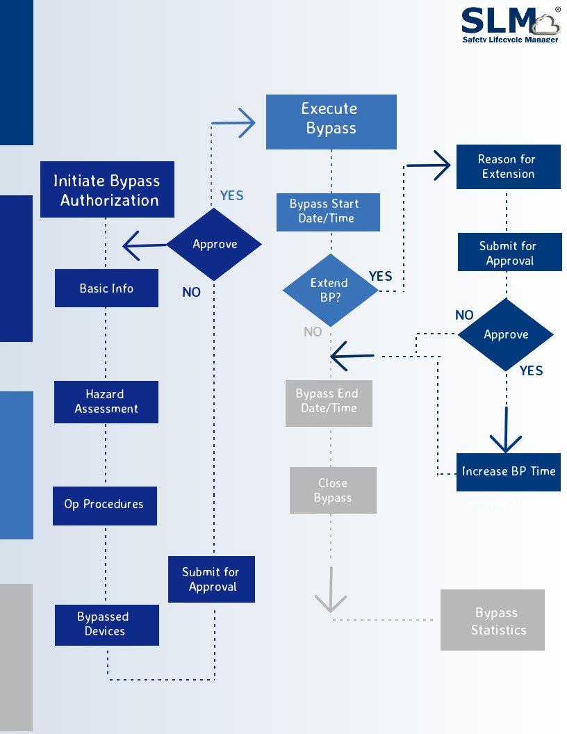
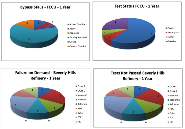
Mangan’s SLM™ software streamlines and automates the complex process of managing safety instrumented systems, enabling organizations to maintain compliance with IEC 61511 efficiently. It provides a comprehensive suite of tools for design, verification, validation, and documentation, helping companies reduce risks, minimize costly errors, and ensure regulatory compliance. 

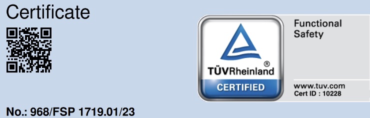
To achieve TÜV re-certification for IEC 61511 compliance, Mangan Software Solutions underwent rigorous testing and evaluation of its SLM™ software by TÜV Rheinland, a globally recognized independent certification body. The successful re-certification underscores the software’s reliability, accuracy, and adherence to international safety standards. 

Download TÜV Certificate: https://fs-products.tuvasi.com/certificates?cert_id=10228


“We are thrilled to receive TÜV certification for our Safety Lifecycle Manager software,” said Jeremy Lucas, President & CTO at Mangan Software Solutions. “This achievement reflects our unwavering commitment to providing our customers with best-in-class solutions that enhance safety, reduce operational risks, and streamline compliance processes. With the certification in place, our clients can have even greater confidence in the capabilities of our SLM™ software to meet and exceed industry safety standards.” 

Mangan Software Solutions’ SLM™ software offers numerous benefits to organizations, including improved safety, reduced downtime, lower operational costs, and simplified compliance management. Its user-friendly interface and powerful features make it an essential tool for companies seeking to enhance their safety instrumented system performance while ensuring regulatory compliance. 

As Mangan Software Solutions continues to innovate and expand its portfolio, the TÜV certification for IEC 61511 compliance further establishes the company as a trusted partner in the safety and risk management space. 

 For more information about Mangan Software Solutions and its certified Safety Lifecycle Manager software, please visit mangansoftware.com. 

About Mangan Software Solutions: 

Mangan Software Solutions is a leading provider of safety and risk management software solutions for the process industry. With a commitment to innovation and excellence, the company empowers organizations to enhance safety, reliability, and compliance throughout the entire lifecycle of safety instrumented systems. Mangan Software Solutions’ products and services are trusted by industry leaders worldwide. 

Media Contact: 

Sean O’Neill
Technical Solutions Engineer
mangansoftware@gmail.com
(281) 402-2647

About TÜV Certification:

TÜV certification is a globally recognized mark of quality and compliance. Organizations that achieve TÜV certification demonstrate their commitment to meeting and exceeding industry standards and regulations, providing assurance to customers and stakeholders that their products or services are of the highest quality and safety. TÜV certification is particularly valuable in industries where safety, reliability, and compliance are paramount, such as the process industry. 

Certificate/Reg.-No.  968/FSP 1719.01/23 

Download TUV Certificate: https://fs-products.tuvasi.com/certificates?cert_id=10228

Moving Existing Data into the SLM® solution

Moving Existing Data into the SLM® solution

When considering whether to move Safety Lifecycle Management into the SLM® solution, the question “What do I do with my existing data?” arises. This was a significant concern when the SLM® software was being developed and has thus been addressed. SLM® software has an Adapter Module that provides the tools for importing data into the SLM® system and exporting data to external systems. Import Adapters use an intermediate .csv file, typically created in Excel, to organize data so that the SLM® software can read the data, create the correct object hierarchy, and then import the data into SLM® software data fields. The software import process is illustrated in the figure below


import_image
During planning for an SLM® software installation, the user and Mangan Software Solution staff will review the data that is available for import and identify what Adapters are needed to support data import. During this review, the linkages between Modules and data objects should be reviewed to ensure that after import objects such as HAZOP Scenarios, LOPA’s, IPL Assets, and Devices are properly linked. If large amounts of data from applications for which an Adapter has not yet been created, it usually is advisable to have the MSS team create a suitable Adapter instead of attempting to use a Generic Import Adapter.

Once the user’s data has been exported to the intermediate .csv file a data quality review and clean up step is advisable. Depending upon the data source, there are likely to be many internal inconsistencies that are much easier to correct prior to import. These may be things as simple as spelling errors, completely wrong data, or even inconsistent data stored in the source application. I recall a colleague noting after a mass import from a legacy database to a Smart Plant Instrument database – “I didn’t realize how many ways there were to incorrectly spell Fisher.”

Once the data has been imported, correcting such things can be very tedious unless you are able to get into the database itself. For most users, errors such as this get corrected one object at a time. However, editing these types of problems out of the .csv file is pretty quick and simple as compared to post import clean up.

To Import the data, the User goes to the Adapter Module and choses the desired Import Adapter and identifies the .csv file that contains the data. The SLM® solution does the rest.
It should also be noted that SLM® software is capable of exporting data too. The User selects data types to export along with the scope (e.g. a Site or Unit). The exported data is in the form of a .csv file. This can be used to import data into a 3rd party application, or to use a data template to import more data.

Rick Stanley has over 40 years’ experience in Process Control Systems and Process Safety Systems with 32 years spent at ARCO and BP in execution of major projects, corporate standards and plant operation and maintenance. Since retiring from BP in 2011, Rick has consulted with Mangan Software Solutions (MSS) on the development and use of MSS’s SLM Safety Lifecycle Management software and has performed numerous Functional Safety Assessments for both existing and new SISs.

Rick has a BS in Chemical Engineering from the University of California, Santa Barbara and is a registered Professional Control Systems Engineer in California and Colorado. Rick has served as a member and chairman of both the API Subcommittee for Pressure Relieving Systems and the API Subcommittee on Instrumentation and Control Systems


Digitalizing Safety Information into Intelligence

Digitalizing Safety Information into Intelligence

What is Digital Transformation and how can the SLM® system help?
Digital Transformation is the process of converting non-digital or manual information into a digital (i.e. computer-readable) format. For an organization, a phase of digital transformation is a great opportunity for organizations to take a step back and evaluate everything they do, from the basic operations to complex workflows.

<p?
Digital transformation is a time to understand the potential opportunity involved in a technology investment. It’s an ideal time to ask questions, such as ‘Can we change our processes to allow for great efficiencies that potentially allow for better decision making and cost savings.’ A perfect example could be trending data to identify optimum test intervals based on degradation over time. This could provide cost savings in fewer required tests.

Advantages of Digital Transformation

The key tactical benefit of digital transformation is to improve the efficiency of core business processes. In the image below, you can see the efficiencies provided by digital data broken down into three key module areas:

SLM benefits

As you can clearly see, the opportunities provided by digitalization are vast and for this reason Digitalization Demands an Integrated Safety Lifecycle Management System A lot of tools in the market today are single purpose and do not share or exchange data in a way suited to a Safety Lifecycle Management system

Common problems

A lot of organizations we speak with are struggling with lagging indicators and poor reporting systems. This degradation has only gotten worse over time, and this points to a lack of clear and accurate data, overly complex workflows and restrictions brought about by company culture.

At any given point in time organizations are unable to identify the current health of their plant and assets. Bad actors are exceedingly difficult to identify and experience is diminishing with retirements and a reduction in the numbers of subject matter experts.

Digital Transformation Solution

Process Safety and Functional Safety is more than just hardware, software, testing and metrics. Taking a holistic approach and instilling a culture of safety requires a complete end-to-end system that can manage from Initial Hazard Analysis to the final Operations & Maintenance. The SLM® system is the only enterprise platform proven to bring together all aspects of the Safety Lifecycle through digital transformation.

Let SLM® be your digital twin

Let SLM® be your digital twin

Digital twins are powerful virtual representations to drive innovation and performance. Imagine it as a digital replica of your most talented product technicians with the most advanced monitoring, analytical, and predictive capabilities at their fingertips. It is estimated that companies who invest in digital twin technology will see a 30 percent improvement in cycle times of critical processes.

A digital twin captures a virtual model of an organization and helps accelerate strategy. This could be in products, operations, services, and can even help drive the innovation of new business. The model can identify elements that are hindering or enabling strategy execution and suggests specific recommendations based on embedded pattern recognition. Digital twin technology is used to collect more dots and connect them faster, so you can drive to better solutions with more confidence.


digital_twin_cloud

Today’s organizations are complex, evolving systems, built on the collective ambitions and talents of real people operating in a dynamic culture. The world is increasingly defined by data and machine learning, however, there is no simple way to measure human motivation or clear-cut formula for building an effective future.

In a nutshell a digital twin is a tool that can be used to analyze your business to identify potential concerns in any area, and show you how those issues link together. Armed with that information, you can build solutions immediately and overcome the most important obstacles – all before they happen. Get in touch and let our Safety LIfecycle Management tools manage your digital needs.

How to Manage Bypasses Using SLM

How to Manage Bypasses Using SLM

IEC 61511 Part 1, contains extensive discussions of the design and operating procedures for SIF bypasses. Clause 16.2 describes operational requirements such as:

  • Performing a hazard analysis prior to initiating a bypass
  • Having operational procedures in place for when a protective function has been bypassed
  • Logging of all bypasses.

How to Manage Bypasses Using SLM – through a robust Bypass management and logging function that meets all of the requirements of IEC-61511 and integrates with the performance analysis and reporting functions of the SLM Operate-Maintain (OM) Module. SLM OM Module uses the Bypass Authorization object and Work Flow to initiate, approve and record the execution of Protective Function Bypasses. SLM does not limit the use of Bypasses to just SIFs. In SLM, any protective function may have a Bypass Authorization associated with it.

Read more about the Benefits of Effective Bypass Management 

The figure below illustrates how the Work Flow supports the tasks required on how to manage bypasess using SLM:

A Bypass Authorization is initiated by any authorized SLM user. In practice this will usually be a member of the Operations Staff for a Unit, often a shift foreman or Operations Engineer. The originator is guided to enter the information required to support the Bypass Authorization. This includes:

  • Basic Bypass information such as the reason for the Bypass, the anticipated start date and time and the maximum time which the Protective Function is to be Bypassed
  • Hazard Assessment information – this includes an identification and assessment of the potential severity of hazards that may occur while the Protective Function is Bypassed and the corrective measures that should be taken if the hazard occurs
  • Operation Procedures that are required to be used to mitigate potential hazards that may occur while the Protective Function is Bypassed
  • Identification of the Devices associated with the Protective Function that will be Bypassed

Once this information is provided, the user then may submit the Bypass Authorization for Approval. The Bypass Authorization is submitted to the designated Approver, typically an Operations Supervisor of Manager. The Approver reviews the Bypass Authorization and either Approves or Disapproves the request.

Once the Bypass Authorization is Approved, the Operations team may execute the Bypass as planned. The originator or other authorized user may then record the start date and time of the Bypass in the Bypass Authorization. If a Bypass is expected to exceed the time requested in the original Bypass Authorization submittal, the user may request approval for a Bypass Extension by filling in the data in the Bypass extension section of the Bypass Authorization object. When approved, this will update the authorized Bypass time and prevent the Bypass from being reported as exceeding its authorized time.

When the Bypass is completed, the originator or other authorized user then enters the date and time when the Protective Function is returned to service and then close the Bypass Authorization. Closing of the Bypass Authorization results in the Bypass data being added to the SLM Events that are used to analyze Protective Function and Device performance.

SLM contains performance views that capture all Bypasses for a Function, Unit and Site. The analysis functions include reporting on the number of bypasses, time in bypass and identification of Bypass Events that exceeded the authorized bypass time. SLM will also compute the effect of Bypasses on a Protective Function’s in-service performance, such as computing the in-service reduction in the Functions’ RRF or PFD. Functions that have excessive Bypasses will also show up on the Unit and Site bad actors lists.


Rick Stanley has over 40 years’ experience in Process Control Systems and Process Safety Systems with 32 years spent at ARCO and BP in execution of major projects, corporate standards and plant operation and maintenance. Since retiring from BP in 2011, Rick formed his company, Tehama Control Systems Consulting Services, and has consulted with Mangan Software Solutions (MSS) on the development and use of MSS’s Safety Lifecycle Management software.

Rick has a BS in Chemical Engineering from the University of California, Santa Barbara and is a registered Professional Control Systems Engineer in California and Colorado. Rick has served as a member and chairman of both the API Subcommittee for Pressure Relieving Systems and the API Subcommittee on Instrumentation and Control Systems.

Promoting a Sustainable Process Safety Culture

Promoting a Sustainable Process Safety Culture

Promoting a sustainable process safety culture can be difficult. The Chemical Safety Board just issued their report on the November 2014 incident at the DuPont La Porte plant in which 4 people were killed:

Click here to read the full report.

Summary of the Report 

The report reads like so many others highlighting some issues with promoting a sustainable process safety culture.  The root cause was said to have been the fact that site and corporate management failed to implement Process Safety Management Systems. Furthermore, the report also cites multiple failures in the overall management of Process Safety. The core failure in this incident was that the facility had a very poor Safety Culture as summarized in the excerpt from the CSB Report. The CSB Report devotes an entire section on how the Process Safety deficiencies in this incident parallel the findings in an earlier CSB report on the 2005 BP Texas City Refinery explosion, despite the site being aware of the report and its findings. ®

DuPont La Porte did not use any type of robust, formal process safety culture assessment. Process safety culture can affect whether a site has a sense of vulnerability in terms of process safety management risks; complacency or overconfidence; and transparent, timely, and thorough responses to PSM concerns, action items, and issues, including leadership measures to prevent a “check-the-box” mentality (i.e., simply accomplishing a task as the objective rather than ensuring a high degree of focus on risk management and prevention). The Safety Perception Surveys conducted at the DuPont La Porte facility before the November 2014 incident were designed to lower OSHA total recordable injury rates [59, p. 8]. DuPont did not intend for these surveys to measure or address the perception of process safety performance.

One of the issues with promoting a sustainable Process Safety culture is that it’s hard without the right tools:

  • The tools that an organization typically has to manage day to day operations don’t fit the needs of Process Safety Management.
  • The tools that do exist are typically single purpose and result in isolation of data and limited availability across organizational boundaries.

It’s extremely easy for individuals to become disconnected as they often are not involved in day to day management of Process Safety and it becomes the perception that it’s taken care of by others. Add a management attitude such as existed at La Porte where there was a misplaced emphasis on measuring personnel safety with no corresponding concern for Process Safety and establishment of a sustainable Process Safety culture becomes impossible.

An effective Process Safety Program needs to make Process Safety information widely available to all employees involved in design, operation, and maintenance of the processes in order to keep them all involved on a daily basis. When a site is using the tools traditionally available for plant operations, information becomes isolated from personnel and is difficult to access. 

Safety Lifecycle Manager (SLM®)                                   

The SLM® application was developed to address the many shortcomings relative to Process Safety that exist in many plants today. The origins of the application were a direct result of the CSB and Baker Panel findings relative to the BP Texas City Refinery explosion.

The objectives of the development of SLM were:

  • Unify Process Safety data in one location so it is accessible to all personnel that need it. This includes PHA, LOPA, IPLs, Plant Assets that perform the functions required by IPLs or other functions, and Field Devices that are used to implement the functions and performance records for Plant Assets and Devices.
  • Provide the tools to perform PHA and LOPA studies within the SLM application.
  • Link Plant Assets to PHA, LOPA, and IPL data so the Process Safety requirements such as LOPA IPLs or PHA Safeguards that resulted in the Plant Assets being installed can be directly accessed from Plant Assets and vice-versa. This provides a very clear linkage between real functions and devices in the plant to the Process Safety reasons that they exist. This addresses the very real issue of IPLs not being clearly identified by LOPA Teams, or multiple LOPA teams identifying multiple IPLs that correspond to the same Plant Asset. The figure below illustrates these relationships.

  • Provide engineering tools that support design of safety instrumented systems (SIS) and safety instrumented functions (SIF) and maximize consistency of design. This includes tools to rapidly develop Safety Requirements Specifications (SRS) and evaluate SIF Probability of Failure upon Demand (PFD). Functional requirements for Safety Related Devices are clearly defined as are testing requirements and any operational requirements.
  • Provide the ability to define functional requirements for other non-SIF Protective Functions and Safeguards and their field Devices including alarms, interlocks, BPCS functions and non-instrumented protective functions.
  • Provide the ability to upload or link key documents directly with Process Safety related Assets. These may be operation and testing procedures or other documents or drawings.
  • Provide a complete Life Cycle management capability that allows for management of Protective Functions during operation and maintenance after initial design and installation. Events associated with the operation of Safety Related Plant Assets such as Demands, Testing, Bypasses and Failures may be recorded using simplified and consistent Work Flows. The figure below illustrates the relationship of Events to Plant Assets and Devices.

  • Provide a real time view of the performance of Protective Functions and their field Devices based upon the Event data contained in the database. Various Key Performance Indicators (KPI) allow the plant to understand the current state of performance and manage periodic testing and identify bad actors for which corrective action is required. Examples of various KPI’s are shown below.

How SLM® can help when promoting a sustainable Process Safety Culture

  • Instead of separation of various aspects of Process Safety, they are integrated in one web-based application that makes Process Safety information available to all personnel who have Process Safety interests.
  • SLM® allows personnel with Process Safety responsibilities to participate in Process Safety Management on a routine basis. Furthermore, personnel that are closest to various Events may be assigned responsibility to record those Events.

For example:

Operations personnel are responsible for entering Events for operational related items such as Demands, Bypasses, and Failures while maintenance personnel are responsible for monitoring testing that is approaching its due date as well as entering the results of testing and any other maintenance Events. This keeps personnel involved in the day to day management of Process Safety related Assets.

Rick Stanley has over 40 years’ experience in Process Control Systems and Process Safety Systems with 32 years spent at ARCO and BP in execution of major projects, corporate standards and plant operation and maintenance. Since retiring from BP in 2011, Rick formed his company, Tehama Control Systems Consulting Services, and has consulted with Mangan Software Solutions (MSS) on the development and use of MSS’s Safety Lifecycle Management software.

Rick has a BS in Chemical Engineering from the University of California, Santa Barbara and is a registered Professional Control Systems Engineer in California and Colorado. Rick has served as a member and chairman of both the API Subcommittee for Pressure Relieving Systems and the API Subcommittee on Instrumentation and Control Systems.


What Went Wrong With The Process Safety System? Lessons From The 737 Max Crash

What Went Wrong With The Process Safety System? Lessons From The 737 Max Crash

 When there is a major accident somewhere, you have to investigate what errors might have been made that contribute to it.  Boeing’s problem with the 737 Max crash highlights a few fundamental issues with the process safety system that need to be examined.

4 Lessons Learned: 

1.)  An extremely important part of the specification of a Process Safety System is to seriously consider the effects of a spurious trip on the overall safety of a process. They really should be designed to keep you out of trouble, and not to put you into it. If a spurious trip could at any point drive a process to an unsafe condition, there needs to be some careful thinking about how that unsafe condition can be avoided. In the 737 Max case, there are indications that operation of the Maneuvering Characteristics Augmentation System (MCAS) at low altitudes may have not been examined as carefully as it should have been.

2.)  The second issue is the lack of a robust system. From reports so far, it appears that the MCAS operated based on only one sensor, which made the system much more exposed to a spurious trip. The failure of the one and only sensor resulted in behavior that drove two planes into the ground. When designing a Process Safety System that could have unsafe behavior if a spurious trip occurs, having a robust system is really important in order to cope with any potential errors. Designing a system that prevents the airplane from going down extremely fast deserves more than one sensor. From the reports this appears to have finally dawned on Boeing’s engineers after two crashes in 5 months.

Airplane Wing

3.)  This might not entirely be the engineer’s fault who designed the system- there was a second sensor known to be available as an option. This suggests managers could have possibly tried to force the unsafe systems to save some money.

4.)  The last issue is relying on people that operate the plane rather than the safety system itself. That only leaves room for human error.   This suggests a robust system wasn’t not required because the pilots were expected to be able to turn off the system if they needed to. This appears to have been successful in some of the reported incidents from US airlines. However, in the actual crashes that occurred, it is being discussed that the flight crews either could not or did not turn off the system. There is some speculation that their training wasn’t sufficient, but in any case, people under a lot of stress tend to forget things and make mistakes.

People can’t be expected to respond to unexpected events reliably. It’s worse if they haven’t been well trained, or it’s been a long time since they were trained. Expecting operator response comes with a burden to train well and train often.

Summary:

The 737 Max crashes are a stark reminder that when designing a safety system responsible for the lives of people, it deserves healthy portions of realism, pessimism, and all around potential risk consideration. You really need to spend time thinking before deciding that a design is acceptable even if there are other pressures from management. 

Infographic of lessons from a plane crash


Rick Stanley has over 40 years’ experience in Process Control Systems and Process Safety Systems with 32 years spent at ARCO and BP in execution of major projects, corporate standards and plant operation and maintenance. Since retiring from BP in 2011, Rick formed his company, Tehama Control Systems Consulting Services, and has consulted with Mangan Software Solutions (MSS) on the development and use of MSS’s SLM Safety Lifecycle Management software.

Rick has a BS in Chemical Engineering from the University of California, Santa Barbara and is a registered Professional Control Systems Engineer in California and Colorado. Rick has served as a member and chairman of both the API Subcommittee for Pressure Relieving Systems and the API Subcommittee on Instrumentation and Control Systems.