Mangan Software Solutions Achieves TÜV Certification for SLM™ Safety Lifecycle Manager

[Houston, October 10, 2023] — Mangan Software Solutions, a leading provider of safety and risk management software solutions, is proud to announce that its Safety Lifecycle Manager (SLM™ v2.5) software has received TÜV re-certification for compliance with the International Electrotechnical Commission (IEC) 61511 standard. This certification represents a significant milestone in Mangan’s commitment to delivering industry-leading solutions that enhance safety and reliability in process industries. 

 IEC 61511 is a globally recognized standard for the functional safety of safety instrumented systems (SIS) in the process industry. It provides a framework for managing the entire safety lifecycle, from concept to decommissioning, and is crucial for ensuring the safety of critical processes in sectors such as chemical, oil and gas, and manufacturing. 

Mangan’s SLM™ software streamlines and automates the complex process of managing safety instrumented systems, enabling organizations to maintain compliance with IEC 61511 efficiently. It provides a comprehensive suite of tools for design, verification, validation, and documentation, helping companies reduce risks, minimize costly errors, and ensure regulatory compliance. 

To achieve TÜV re-certification for IEC 61511 compliance, Mangan Software Solutions underwent rigorous testing and evaluation of its SLM™ software by TÜV Rheinland, a globally recognized independent certification body. The successful re-certification underscores the software’s reliability, accuracy, and adherence to international safety standards. 

Download TÜV Certificate: https://fs-products.tuvasi.com/certificates?cert_id=10228


“We are thrilled to receive TÜV certification for our Safety Lifecycle Manager software,” said Jeremy Lucas, President & CTO at Mangan Software Solutions. “This achievement reflects our unwavering commitment to providing our customers with best-in-class solutions that enhance safety, reduce operational risks, and streamline compliance processes. With the certification in place, our clients can have even greater confidence in the capabilities of our SLM™ software to meet and exceed industry safety standards.” 

Mangan Software Solutions’ SLM™ software offers numerous benefits to organizations, including improved safety, reduced downtime, lower operational costs, and simplified compliance management. Its user-friendly interface and powerful features make it an essential tool for companies seeking to enhance their safety instrumented system performance while ensuring regulatory compliance. 

As Mangan Software Solutions continues to innovate and expand its portfolio, the TÜV certification for IEC 61511 compliance further establishes the company as a trusted partner in the safety and risk management space. 

 For more information about Mangan Software Solutions and its certified Safety Lifecycle Manager software, please visit mangansoftware.com. 

About Mangan Software Solutions: 

Mangan Software Solutions is a leading provider of safety and risk management software solutions for the process industry. With a commitment to innovation and excellence, the company empowers organizations to enhance safety, reliability, and compliance throughout the entire lifecycle of safety instrumented systems. Mangan Software Solutions’ products and services are trusted by industry leaders worldwide. 

Media Contact: 

Sean O’Neill
Technical Solutions Engineer
mangansoftware@gmail.com
(281) 402-2647

About TÜV Certification:

TÜV certification is a globally recognized mark of quality and compliance. Organizations that achieve TÜV certification demonstrate their commitment to meeting and exceeding industry standards and regulations, providing assurance to customers and stakeholders that their products or services are of the highest quality and safety. TÜV certification is particularly valuable in industries where safety, reliability, and compliance are paramount, such as the process industry. 

Certificate/Reg.-No.  968/FSP 1719.01/23 

Download TUV Certificate: https://fs-products.tuvasi.com/certificates?cert_id=10228

Issues With Managing Process Hazard Analysis (PHA) Data

Issues With Managing Process Hazard Analysis (PHA) Data


 National and local regulations require that all process operations have a formal Hazards Analysis performed on the original installation as well as for all modifications to the facility. Most regulations also require that the Process Hazard Analysis (PHA) of record be re-validated at regular intervals, such as the 5-year re validation cycle required in the US. 

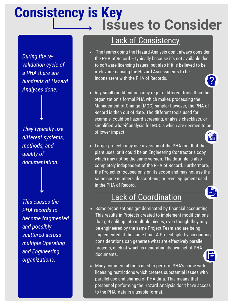
PHA is a complex tool used during the lifecycle of a facility and two of the biggest issues with them are coordination and consistency (see figure 1 below).  A PHA of Record represents a point in time, but in reality plant cycles are not static.  They are actually very dynamic with multiple independent modifications in progress. Some records are implemented even though the plant is in operation while a backlog of modifications are scheduled for the next turnaround.  They start collecting the day the plant is started up after its last turn around. Every time a plant is modified, some form of PHA is performed. The scope of these modifications can range from a small in-house modification to large projects that expand, de-bottleneck, or fix the process.

Figure 1:

So, in a real plant environment, the Process Safety Management (PSM) Teams are faced with the almost impossible task of monitoring and collecting all of the completed Hazard Assessments and incorporating them into the PHA of Record as the modifications are implemented. If this hasn’t been done as time goes along, the PSM team then has an even bigger job of collecting all the incremental changes and identifying how they relate to the PHA of Record before they start the Re-validation process. All is a lot of work and consumes several full-time equivalents of work just to keep up. Most places don’t have these resources, so they make due as best they can.

SLM® for Process Safety Solution

SLM® for Process Safety Solution

Mangan Software Solutions (MSS) is a leading supplier in the Process Safety and Safety Lifecycle software industry. For the past decade, MSS has been leading the market in innovative technologies for the Refining, Upstream Oil & Gas, Chemical, Pipeline, and Biopharmaceutical industries, transforming Process Safety Information into Process Safety Intelligence. MSS’ engineers and programmers are experts in the fields of Safety Lifecycle Management and Safety Instrumented Systems. With a scalable software platform and years of experience working with the premier energy companies in the world, MSS has established itself as the leader in software solutions engineered specific to the clients’ needs.


Process Safety Solutions


SLM® HAZOP Module

With our market leading SLM® software our clients are able to conduct, review, report, and approve HAZOP studies in one place without tedious work in Excel or other closed toolsets that keep you from your data.

The SLM® HAZOP module ensures HAZOP Study uniformity across the enterprise and ensures reporting is standardized and consistent.  It allows direct comparison of hazard and risk assessment between sites or units.

Using our SLM® Dynamic Risk Matrix visually identifies enterprise hazards and risk.. The HAZOP Study data can be filtered based on site, unit, health & safety, commercial, or environmental criteria.

Safety_Life_Framework

SLM® LOPA Module

The SLM® LOPA module now provides intuitive worksheets to standardize your LOPA process and conduct IPL assessments. The Dynamic Risk Matrix is configurable to your risk ranking system and severities and offers real-time risk monitoring and identification. Dynamic reports and KPIs reveal unmitigated risks to allow for IPL gap closure scheduling and progress status. These reports offer unprecedented review of risk mitigation strategies.


hazop-lopa

SLM® Action Item Tracker Module

Identify risks and safeguards and track them with action items from HAZOP meetings through to the implementation of an IPL. The SLM® Action Item Tracker module is a centralized area where users can access assigned action item information pulled from all modules for action or reporting. Data relating to the action item is linked across modules and readily available for reference purposes. Customized reports and KPIs are available with a click of the mouse.

Hazop-of-record

SLM® Functional Safety Assessment Module

The SLM® Functional Safety Assessment (FSA) module allows you to readily complete a Stage 1 through Stage 5 FSA in a standardized format – ensuring consistency throughout your organization. This tool allows you to define requirements for an FSA and then use the application to improve the effectiveness and efficiency of execution.

linking-ipls

Dean Edit – Digitalization Demands An Integrated Safety Lifecycle Management System (part 1)

Dean Edit – Digitalization Demands An Integrated Safety Lifecycle Management System (part 1)

An integrated safety lifecycle management system is crucial to properly manage the entire safety lifecycle from cradle to grave. Anyone who has attempted to manage the Safety Lifecycle has quickly realized that the tools that a typical processing facility uses are wholly unsuited to meet the requirements of the Safety Lifecycle.

Most tools available are single purpose and don’t exchange or share information. The tools available are directed towards managing things such as costs, labor management, warehouse inventory management, and similar business-related functions. The systems upon which these functions are based generally use a rigid hierarchy of data relationships and have little flexibility.

An Integrated Safety Lifecycle Management program must supplement or replace the traditional tools to even be considered.  Otherwise, the result is a mix of paper files (or image files on network drives)and a variety of independent word processor and spreadsheet files.  Not to mention the procedures for data collection that fall outside of what the traditional plant management tools will do. This places an unreasonable and unsustainable burden on plant personnel. These systems may be forced to work for awhile, but don’t perform well over time.  Also, its necessary to consider changes of personnel in various positions that occur.

Safety Lifecycle Management

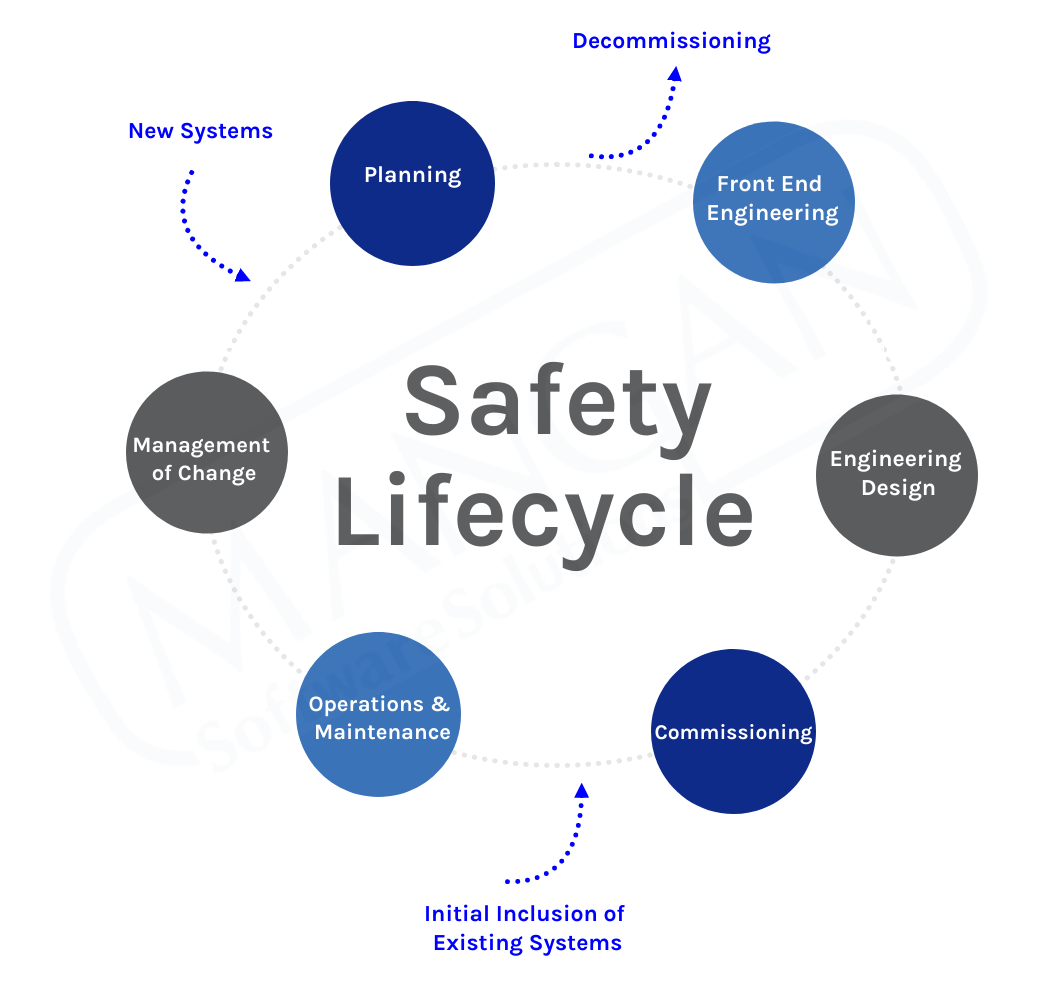
The Safety Lifecycle is a continuous process that originates with the conceptual design of a processing facility and continues throughout the entire service life of that process. Process Safety related functions start their life during the initital Hazard Assessments when potential hazards and their consequences are evaluated. Protective functions are designed to prevent the consequences of the hazards from occurring and their lifecycle proceeds through design, implementation and operation. As plant modifications occur, the existing functions may need to be modified,may be found to no longer be necessary, or new functions are identified as being required. This results in another trip through the lifecycle as illustrated below.

The Safety Lifecycle IEC Regulations  

 IEC 61511, defines the processes that are to be followed when developing, implementing and owning of Safety Instrumented Systems (SIS). While the scope of IEC 61511 is limited to SIS, the concepts also apply to other Protective Functions that have been identified such as Basic Process Control Functions, Interlock, Alarms or physical Protective Functions such as barriers, drainage systems, vents and other similar functions.

The Safety Lifecycle as described in IEC 61511 is shown in the figure below. This figure has been excerpted from IEC 61511 and annotated to tie the various steps with how Process Safety Work is typically executed. These major phases represent work that is often executed by separate organizations and then is passed onto the organizations responsible for the subsequent phase. 


Safety lifecycle management process diagram

1.) Requirements Identification

This phase involves conducting Process Hazards Analyses and identifying the Protective Functions required to avoid the consequences of process hazards from occurring.

The tools typically used for these activities are a Process Hazards Analysis application and Layers of Protection Analysis (LOPA). The CCPS publication Layer of Protection Analysis: Simplified Process Risk Assessment describes the process of identification and qualification of Protective Functions, identified as Independent Protection Layers (IPL’s).

2.)  Specification, Design, Installation and Verification 

This phase is typically thought of as “Design”, but it is so much more:

  • The Specification phase is involving specification of the functional requirements for the identified IPL’s. When the IPL’s are classified as Safety Instrumented Functions (SIF), they are defined in a Safety Requirements Specification as defined by IEC 61511. Other non-SIF IPL’s are defined as described in the CCPS LOPA publication, although the concepts defined in IEC 61511 are also an excellent guide.
  • Once requirements are specified, physical design is performed. The design must conform to the functional, reliability and independence requirements that are defined in the SRS or non-SIF IPL requirements specifications.
  • The designs of the Protective Functions are installed and then are validated by inspection and functional testing. For SIS’s a Functional Safety Assessment as described by IEC 61511 is performed prior to placing the SIS into service.

3.) The Ownership Phase

This is the longest duration phase, lasting the entire life of the process operation. This phase includes:

  • Operation of the process and its Protective Functions. This includes capture of operational events such as Demands, Bypasses, Faults and Failures.
  • Periodic testing of Protective Functions at the intervals defined by the original SRS or IPL requirements. This involves documentation of test results and inclusion of those results in the periodic performance evaluations.
  • Periodic review of Protective Function performance and comparison of in-service performance with the requirements of the original SRS or IPL requirements. If performance is not meeting requirements of the original specifications, identification and implementation of corrective measures is required.
  • Management of Change in Protective Functions as process modifications occur during the process lifetime. This starts a new loop in the Safety Lifecycle where modifications, additions or deletions of Protective Functions are identified, specified and implemented.
  • Final decommissioning where the hazards associated with decommissioning are assessed and suitable Management of Change processes are applied.


CLICK HERE TO READ MORE ON ⇨ A Holistic Approach to the Safety Lifecycle


Execution Challenges

Execution of the Safety Lifecycle interacts with numerous process management tools. Some of those tools that are typically available are illustrated in the figure below. All of these tools have the characteristics that they are generally suitable for the single purposes for which they were chosen, but all of them have limitations that make them unsuitable for use with a Safety Lifecycle Management process.

The Safety Lifecycle involves numerous complex relationships that cross traditional organizational boundaries and require sharing of data across these boundaries. The tools traditionally used in process operational management just don’t fit the requirements of Managing the Safety Lifecycle. Attempts to force fit them to Safety Lifecycle Management results in fragmented information that is difficult to access and maintain or which is just missing, and which results in excessive costs and highly ineffective Safety Lifecycle Management. The work around become so fragmented and complex, they rapidly become unsustainable. 

SRS and SIS engineer data
  • The Value of an Integrated Safety Lifecycle Management System

    An Integrated Safety Lifecycle Management System provides the benefits that an organization expects from the protective systems installed in a facility. The System provides fit for purpose work processes that account for the multiple relationships among the various parts of the Safety Lifecycle that traditional tools do not provide. A few of the high-level benefits are:

        • Consistency and quality of data is vastly improved by using common processes, data selection lists, data requirements and procedures that have been thought out and optimized for the needs of managing protective systems.
        • Design of Protective Functions is made much more efficient due to standardization of the information needed and the ability to copy SRS and non-SIF IPL data from similar applications that exist elsewhere in an organization. Design data is readily available to all authorized Users that need that data.
        • Process Safety awareness is enhanced because the Safety Lifecycle Management System provides links between the originating hazard assessments, PHA Scenarios, LOPA’s, LOPA IPL’s and the Plant Assets used to implement the Protective Functions. Authorized users can readily identify Protective Functions and Plant Assets that implement them, and directly access the process hazards for which the functions were installed to prevent.
        • Protective Function and associated Plant Asset performance events can be readily captured with a minimum of effort. The Safety Lifecycle Management System collects all of the event data and automatically produces performance data such as Tests Overdue, Tests, Failure Rates, Tests Upcoming, Demand Rates, Failure Rates and Prior Use statistics on a real time basis. The performance can be reported on a Unit, Site or Enterprise basis and can be categorized by Protective Function type, Device Type, Device manufacturer or similar categories. This allows Users to fully understand the conformance of Protective Function and Device performance relative to their Safety Requirements and identify any performance issues.


 Rick Stanley has over 45 years’ experience in Process Control Systems and Process Safety Systems with 32 years spent at ARCO and BP in execution of major projects, corporate standards and plant operation and maintenance. Since retiring from BP Rick has consulted with Mangan Software Solutions (MSS) on the development and use of MSS’s SLM Safety Lifecycle Management software and has performed numerous Functional Safety Assessments for both existing and new SISs.

Rick has a BS in Chemical Engineering from the University of California, Santa Barbara where he majored in beach and minored in Chemical Engineering… and has the grade point to prove it. He is a registered Professional Control Systems Engineer in California and Colorado. Rick has served as a member and chairman of both the API Subcommittee for Pressure Relieving Systems and the API Subcommittee for Instrumentation and Control Systems.

See how industry leaders like Shell are digitizing their process safety lifecycle!

Justifying Investment in a Safety Lifecycle Management (SLM) Platform

You have seen the SLM® demonstration and are impressed. Every process safety, safety engineering and operations challenge that you threw at the demonstration team has been answered. The software has a well-designed and user friendly solution for every problem except one: How do you sell this to your management?

This paper discusses how safety lifecycle software purchases may be effectively justified to your senior management through both business and safety case studies from actual customer experiences. Your numbers will likely differ from the numbers used in these case studies, but this paper should help you understand where to look.

Please complete the form below and you will be redirected to your download.

3 + 3 =

Leveraging Prior use to Build an Actionable Instrumentation Reliability Database

As increasing attention falls upon managing Safety Instrumented Systems (SISs), industry leaders are looking for more reliable device and equipment options when designing their safety instrumented functions – the goal being to achieve the highest possible Risk Reduction Factor (RRF) per instrumented function, while minimizing construction and maintenance costs.

Please complete the form below and you will be redirected to your download.

12 + 7 =

Hydrocarbon Processing

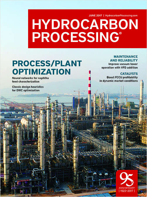
Over the past 25 years, the process safety and functional safety disciplines have evolved from the implementation of safety legislation and the creation of governing authorities, to the de-development of best practices and the adoption of applicable standards. As the push for operational excellence and process safety spreads across multiple industries worldwide, organizations are continuously looking to technology to offer effective solutions.

Over that time, technological advances have provided new and effective software products that sought to answer this call; yet, emerging process safety methodologies and technical limitations of the 1990s and early 2000s reduced their scope and efficacy. Detailed here are the evolution of information-man- management technology, the benefits of software innovation over the last 25 years, and the limitations of tactical solutions that led to the search for new products.

Please complete the form below and we will send your whitepaper to you.

9 + 6 =

Safety Requirements Specifications – They don’t have to be hard (or expensive)

IEC 61511 and ISA 84.00.01-2004, Clause 10, requires that a Safety Requirements Specification (SRS) be prepared for all Safety Instrumented Systems (SISs). The Clause presents a number of items to cover in the SRS, but provides little or no guidance on how a SRS should be developed, organized, or maintained. This lack of guidance results in Operating Companies, SIS Consultants, and Engineering Companies producing a variety of SRSs that vary widely in format, content, and quality. In practice, these SRSs have become extremely expensive to produce and maintain, and really do not meet the intended functionality and value.

This white paper reviews the purpose and usage of a SRS, identifies some issues observed in SRSs produced by various organizations, provides some practical suggestions for SRS preparation, and discusses the advantages of a Data-Driven SRS.

Please complete the form below and you will be redirected to your download.

9 + 9 =

The Business Case for Integrated Safety Lifecycle Management

Safety Lifecycle Management roles and functions cross multiple organizational boundaries and require active and continual sharing of data that often does not occur in traditional process facilities. This paper discusses the business reasons for adoption of an integrated Safety Lifecycle Management program. Among the topics discussed are management perceptions relative to Safety Lifecycle Management, obstacles that exist in traditional approaches and how compliance with National and Industry Standards and efficient management of the Safety Lifecycle are good business practices.

Please complete the form below and you will be redirected to your download.

12 + 5 =

Tracking Safety Instrumented System Performance with Process Data

By leveraging the power of real-world device event data and incorporating that data into a SIS Safety Lifecycle Management (SLM) software, plant operations and maintenance teams can gain powerful insights into the performance of their Safety Instrumented Systems (SISs) while responding quickly to maintenance issues. Integration between the systems automates the manual processes of gathering critical data surrounding SISs and simplifies the data exchange surrounding test frequencies, test results, spurious trips, automated event tracking, and overall plant safety. There are many means of accessing and reporting on this real-world and even real-time data. SLM has integration capabilities with open interfaces and flexibility. Users can quickly define and integrate this time-series data stream into Key Performance Indicators (KPIs), report views, test events, and notifications. This complete end-to-end integration of data creates a more complete picture of how to maintain and operate a safer and more efficient plant.

Please complete the form below and you will be redirected to your download.

10 + 11 =