Digital Transformation of Control and Safety Systems
Digital Transformation of Control and Safety Systems
The Digital Transformation of Control and Safety Systems has come a long way. They used to be simple yet were unreliable, not very robust, or died from neglect. In the past, the term Safety System generally wasn’t used very much, rather you would see terms such as ESD and Interlock. The technologies used in the past were often process connected switches and relays that were difficult to monitor, troubleshoot, and maintain. Field instrumentation used 3-15 psig air or 4-20 ma signals. Things have changed since then. They have become more effective yet with that, a lot more complicated as well.
As control systems, safety systems, and field instrumentation were digitized, the amount of data a user has to specify and manage grew by orders of magnitude. Things that were defined by hardware design, that were generally unchangeable after components were specified, became functions of software and user configuration data which could be changed with relatively little effort. This caused the management of changes, software revisions, and configuration data to become a major part of ownership.
The problem is that the market is dominated by proprietary systems that apply only to manufacturers line of products, so the user is required to have multiple software packages to support the wide variety of instrumentation, control systems, safety systems and maintenance management support systems that exist in any of today’s process plants. Here’s an overview of the evolution and landscape of these systems and the relative chaos that still exists.
What are industry leaders like Shell doing to digitally transform their process safety lifecycle?
Field Instrumentation
Back in the early 1980’s an operating company was involved in the first round of process control system upgrades to the first generation of DCS that were available. There were projects for field testing prototypes of a new digital transmitter major manufacturers. The transmitters that were being tested were similar to the 4-20 ma transmitters, but the digital circuity that replaced the old analog circuitry was programmed by a bulky handheld communicator. It took about 10 parameters to set up the transmitter.
Now you can’t buy anything other than a digital transmitter, and instead of a few parameters available, there are dozens. Digital valve controllers have also become common and the number of parameters available number in the hundreds. Device types with digital operation have also exploded, including adoption of wireless and IOT devices. The functionality and reliability of these devices far exceed those of their prior analog circuit-based relatives. The only cost is that someone has to manage all of that data. A binder full of instrument data sheets just doesn’t work anymore.
Field Instrumentation Management Systems
When digital field instrumentation was first introduced the only means of managing configuration data for each device was through a handheld communications device, and the configuration data resided only on the device. This was simple enough when the parameters mirrored the settings on non-smart devices. However, these devices got more sophisticated and the variety of devices available grew. Management of their configuration data became more demanding and the need for tools for management of that data became fairly obvious.
The market responded with a variety of Asset Management applications and extended functionality from basic configuration date management to include calibration and testing records and device performance monitoring. The systems were great, but there was major problem in that each manufacturer had packages that were proprietary to their lines of instrumentation.
There have been attempts to standardize instrument Asset Management, such as the efforts of the FTD group, but to date most users have gravitated towards specific manufacturer software based upon their Enterprise or Site standard suppliers. This leaves a lot of holes when devices from other suppliers are used, especially niche devices or exceptionally complex instruments, such as analyzers are involved. Most users end up with one package for the bulk of their instrumentation and then a mix of other packages to address the outliers, or no management system for some devices. Unfortunately, manufacturers aren’t really interested in one standard.
Communications Systems
As digital instrumentation developed, the data available was still constrained by a single process variable transmitted over the traditional 4-20 ma circuit. The led to development of digital communications methods that would transmit considerable device operation and health data over top of, or in replacement of, the 4-20 ma PV signal. The first of these was the HART protocol developed by one manufacturer but released to the industry as an open protocol. However, other manufacturers developed their own protocols that were incompatible with HART. As with Asset Management software, the market is divided up into competing proprietary offerings and a User has to make choices on what to use.
In the 1990’s, in an attempt to standardize something, the Fieldbus Foundation was established to define interoperable protocols. Maneuvering for competitive advantage led some companies to establish their own consortiums such as Profibus and World FIP that used their own protocols. The field instrument communications world has settled on a few competing and incompatible systems. Today a user basically has to make a choice between HART, Fieldbus, Profibus and DeviceNet, and then use the appropriate, often proprietary, support software and hardware.
Distributed Control Systems and PLC’s
1980 is back when programming devices required customized hardware. The PLC had its own suitcase sized computer that could only be used for the PLC. Again, data was reasonably manageable, but a crude by today’s standards.
Over the years the power of the modules has evolved from the original designs that could handle 8 functions, period, to modules that can operate all or most of a process plant. The industry came up with a new term, ICSS for Integrated. Control and Safety System to describe DCS’s that had been expanded to include PLC functions as well as Safety Instrumented Systems.
The data involved in these systems has likewise exploded as has the tools and procedures for managing that data. The manufacturers of the DCS, PLC and SIS systems have entire sub-businesses devoted to the management of the data associated with their systems.
As with other systems software the available applications are usually proprietary to specific manufacturers. Packages that started out as simpler (relatively speaking) configuration management software were extended to include additional functions such as alarm management, loop turning and optimization, and varying degrees of integration with field device Asset Management Systems.
Safety Instrumented Systems
Safety Instrumented System logic solvers were introduced in the earl 1980’s, first as rather expensive and difficult to own stand-alone systems. The SIS’s evolved and became more economic. While there still are stand along SIS available, some of the DCS manufacturers have moved to offering Integrated Control and Safety Systems (ICSS) in which SIS hardware and software for Basic Process Control (BPCS), SIS and higher-level functions such as Historians and Advanced Control applications are offered within integrated product lines.
As with all of the other aspects of support software, the packages available for configuration and data management for SIS hardware and software is proprietary to the SIS manufacturers.
Operation and Maintenance Systems
The generalized Operation and Maintenance Systems that most organizations use to manage their maintenance organizations exist and have been well developed for what they do. Typically, these packages are focused on management of work orders, labor and warehouse inventory management and aren’t at all suitable for management of control and safety systems.
Most of the currently available packages started out as offerings by smaller companies but have gotten sucked up into large corporations that have focused on extending of what were plant level applications into full Enterprise Management Systems that keep the accountants and bean counters happy, but make life miserable for the line operations, maintenance and engineering personnel. I recall attending an advanced control conference in which Tom Peters (In Search of Excellence) was the keynote speaker. He had a sub-text in his presentation that he hated EMS, especially SAP. His mantra was “SAP is for saps”, which was received by much head nodding in the audience of practicing engineers.
Some of the Operations and Maintenance Systems have attempted to add bolt on functionality, but in my view, they are all failures. As described above, the management tools for control and safety systems are fragmented and proprietary and attempting to integrate them into generalized Operation and Maintenance Systems just doesn’t work. These systems are best left to the money guys who don’t really care about control and safety systems (except when they don’t work).
Process Safety System Data and Documentation
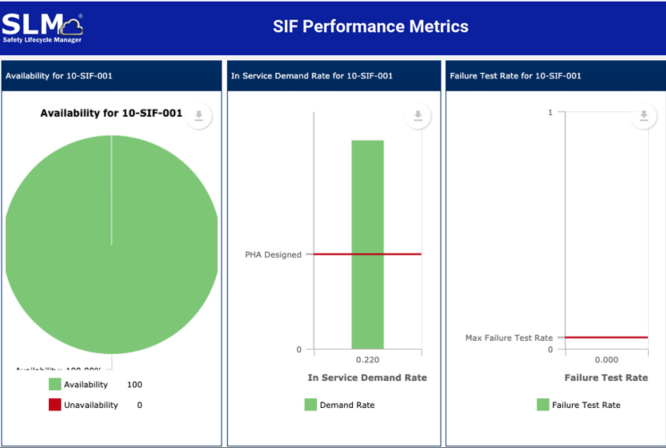
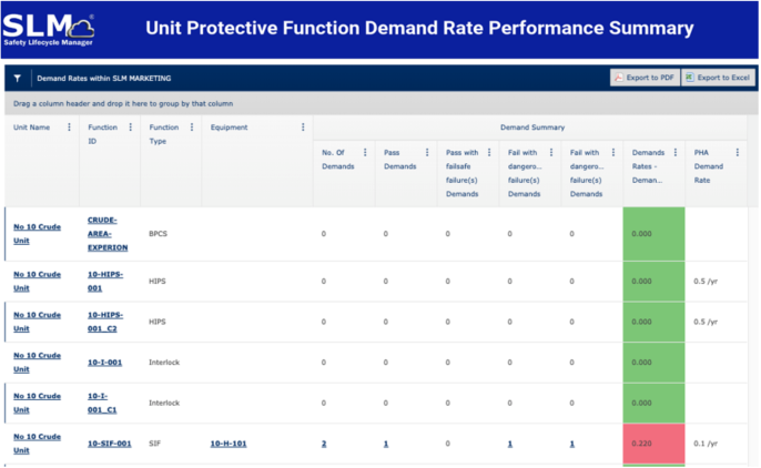
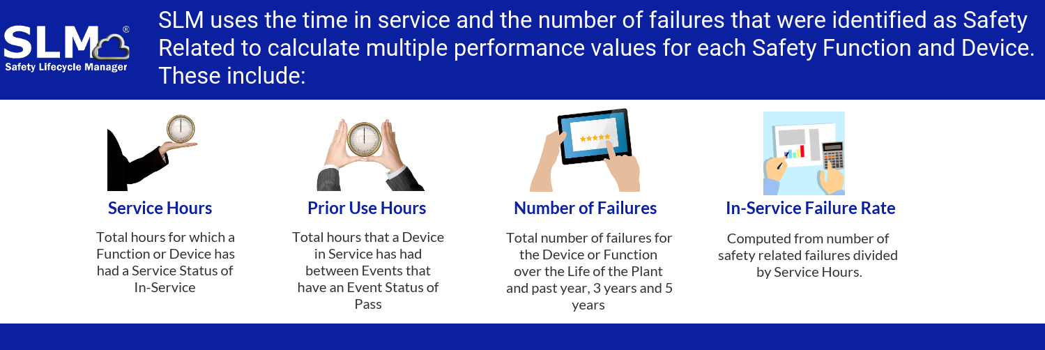
The support and management software for SIS’s address only the nuts and bolts about programming and maintaining SIS hardware. They have no, or highly limited functionality for managing the overall Safety Life Cycle from initial hazard identification through testing and maintaining of protective functions such as SIFs and other Independent Protection Layers (IPLs). Some of the Operation and Maintenance System suppliers have attempted to bolt on some version of Process Safety Management functionality, but I have yet to see one that was any good. In the last decade a few engineering organizations have released various versions of software that integrate the overall Safety Lifecycle phases. The approach and quality of these packages varies. I’m biased and think that Mangan Software Solutions’ SLM package is the best of the available selections. However, The ARC Advisory Group also agrees.
Conclusions
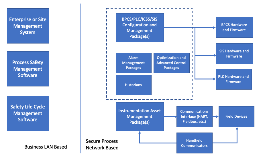
The Digital Transformation of Control and Safety Systems has resulted in far more powerful and reliable systems than their analog and discrete component predecessors. However, the software required to support and manage these systems is balkanized mixed of separate, proprietary and incompatible software packages, each of which has a narrow scope of functionality. A typical plant user is forced to support multiple packages based upon the control and safety systems that are installed in their facilities. The selection of those systems needs to consider the support requirements for those systems, and once selected it is extremely difficult to consider alternatives as it usually requires a complete set of parallel support software which will carry its own set of plant support requirements. Typically, a facility will require a variety of applications which include:
- Field device support software and handheld communicators
- Field device Asset Management Software, typically multiple packages if the User uses multiple suppliers
- DCS/BPCS/PLC/ICSS support software for configuration, alarm management and optimization functions as used by the Site. If a Site has multiple suppliers, then multiple parallel packages are required
- SIS support software for configuration and software management if not integrated with and ICSS software package. If a Site has multiple suppliers, then multiple parallel packages are required
- Operations and Maintenance Management packages – selected by others and not within the control of personnel responsible for Process Control and Safety Systems.
- Safety Lifecycle Management Software – preferably an integrated package that includes Hazard Analysis, Safety Function and System design and Safety Function testing, event data collection and performance analysis and management functions.
So choose wisely.
Rick Stanley has over 40 years’ experience in Process Control Systems and Process Safety Systems with 32 years spent at ARCO and BP in execution of major projects, corporate standards and plant operation and maintenance. Since retiring from BP in 2011, Rick has consulted with Mangan Software Solutions (MSS) on the development and use of MSS’s SLM Safety Lifecycle Management software and has performed numerous Functional Safety Assessments for both existing and new SISs.
Rick has a BS in Chemical Engineering from the University of California, Santa Barbara and is a registered Professional Control Systems Engineer in California and Colorado. Rick has served as a member and chairman of both the API Subcommittee for Pressure Relieving Systems and the API Subcommittee for Instrumentation and Control Systems.