How to Use Your Process Historian to Generate Automated Safety Lifecycle Manager (SLM) Events

How to Use Your Process Historian to Generate Automated Safety Lifecycle Manager (SLM) Events

Capturing Events in SLM generally requires manual entry of data by a user. However, this doesn’t need to be the case. It is possible to automatically extract Event data from a Process Historian. Setting it up takes some initial work, but once the setup has been done, the process of Event generation can be automated.

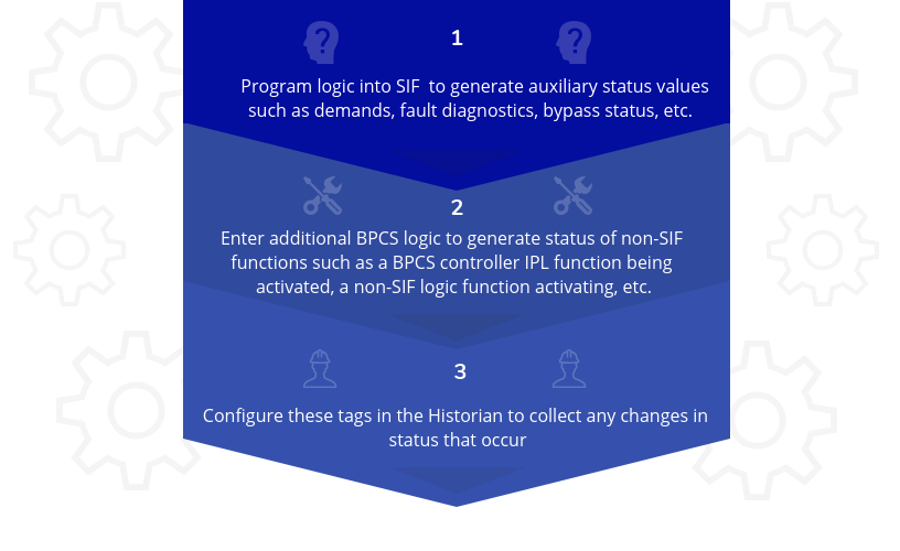
First, the user must have tags that exist in the basic process control system (BPCS) and Historian from which the Historian can capture changes in status. These are status tags that signify that an Event has occurred. A few examples of this are:

  • Alarm Activation
  • Safety Instrumented Function (SIF) Demands
  • Manual Trip Commands
  • SIF Bypasses
  • Fault/Failure Diagnostics
  • BPCS demands

In order to leverage this functionality, the underlying BPCS, Safety Instrumented System (SIS) alarm, and status tags need to be developed. See example in the figure below:


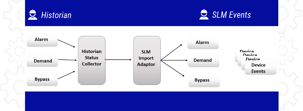
Then, once the necessary status data is available in the Historian, an external scanning program needs to be developed that will scan the Historian data for a set of tags on some routine basis, typically daily, but other intervals may be chosen.

The scanning program exports a file with a list of all status changes that occurred over the scan interval. Typically, this file contains the tag number of the tags associated with the status change, the status change (e.g. from Normal to Tripped, Normal to Bypass, Bypass to Normal, etc.) and the time stamp of the status change. On the SLM side, another program, the SLM Import Adapter, examines the Historian export file and generates the associated Event in SLM. In order to do this, SLM needs to have a table of the tags which may have a status change and enough information to allow SLM to generate the Event. Some of the information required is:

  • The Historian tag name and the SLM object name – These should be the same, but there is no guarantee they will be.
  • The type of Event with which the Historian tag is to be associated (e.g. Demand, Bypass, etc.)
  •  A list of Devices associated with the SLM object name for which SLM should create Device Events
  • Whether the Event is to be directly logged in SLM or submitted for Approval.

The SLM Import Adaptor is then used to generate the SLM Events. The Adaptor handles the messy behind the scenes details of creating the Events and any linkages to SLM Parents or Children. 

However, it should be noted that Historian tag status data cannot always provide all the data that a user may want to support SLM’s performance analysis and reporting functions.

For example, a SIF Demand Event generated from Historian data will record a SIF Demand in SLM, but probably won’t have enough data available to verify whether the Demand was executed successfully or identify what Devices were involved in the Demand.

It will usually be necessary for a user to review the automatically generated Event data and supplement it with additional information such as Pass/Fail status or creating or editing Device Events that should be associated with a Demand. This can be addressed by requiring that all automatically generated Events be entered into the SLM database as requiring Approval. This clearly identifies that new Events have been created and allow for review and completion prior to finalizing the Event.

While we have been discussing how SLM Events can be generated from Historian data, the same concepts can be applied to other Events such as Testing and Maintenance Events where data can be extracted from a Site’s Maintenance Management System and imported to SLM Events. 

Rick Stanley has over 40 years’ experience in Process Control Systems and Process Safety Systems with 32 years spent at ARCO and BP in execution of major projects, corporate standards and plant operation and maintenance. Since retiring from BP in 2011, Rick formed his company, Tehama Control Systems Consulting Services, and has consulted with Mangan Software Solutions (MSS) on the development and use of MSS’s Safety Lifecycle Management software.
Rick has a BS in Chemical Engineering from the University of California, Santa Barbara and is a registered Professional Control Systems Engineer in California and Colorado. Rick has served as a member and chairman of both the API Subcommittee for Pressure Relieving Systems and the API Subcommittee on Instrumentation and Control Systems.

Functional Safety Assessment (FSA) – “A” is for Assessment

Functional Safety Assessment (FSA) – “A” is for Assessment

Functional Safety Assessment VS Functional Safety Audit

 When I chair a Functional Safety Assessment (FSA) for a Safety Instrumented System (SIS), there is usually a brief kickoff meeting with the personnel that will be involved in the assessment such as Engineering, Operations, Maintenance and Process Safety. They are often under the impression that they are being audited. However, that isn’t really the case.

IEC 161511 ed. 2 contains the following definitions:

3.2.24 Functional Safety Assessment (FSA):
Investigation, based on evidence, to judge the functional safety achieved by one or more SIS and/or other protection layers.

3.2.25 Functional Safety Audit:
Systematic and independent examination to determine whether the procedures specific to the functional safety requirements comply with the planned arrangements, are implemented effectively and are suitable to achieve the specified objectives.

An FSA is not intended to be a systematic deep dive into all aspects of the execution of Safety Life Cycle requirements. It is intended to be a review of the evidence that an organization can present to demonstrate that their activities, procedures and plans comply with the Safety Life Cycle requirements of the IEC/ISA Standards.

The Standards say that the FSA team shall include one senior competent person not involved in the project design team or involved in operation and maintenance of the SIS. That is an incredibly important requirement. The “senior competent person” needs to have the experience and judgment to know what to look for and to be able to assess what is found.

As that “senior competent person” for most FSA’s of which I’ve been the chair, I tend to take an initial high-level review of the documentation I’ve been provided. I’m not checking all the details. However, over my career I’ve been bitten enough times (sometimes by myself) to be able to sniff out where something is missing or where an organization that has produced a portion of the documentation hasn’t really thought about a particular part of the Life Cycle. That is when it may be time for a selective deep dive.

 The important issue is I’m not cross checking every single detail in each document. I’m assessing the overall quality of the documentation given to me, noting what documentation may be missing, and the answers I get when I’m discussing the SIS with various personnel that are involved. Only when I am able to ascertain that something is off is when I begin to devote the time to start looking with a little more attention to detail. When I find things that are incorrect, or incomplete, I will identify them, but I’m not going so deep as to say things like “Step 45 in the proof test procedure isn’t correct”. I’m going to look at the proof test procedure and review it to verify first that it exists and then if executed will it meet its stated objective. The FSA team doesn’t have the time to do a detailed design and documentation quality audit – that is the job of the organization that designs and owns the SIS and it’s an activity that should be done prior to the FSA.

Another aspect is that in most instances, the FSA team has little or no enforcement authority. The team can only identify the issues of concern in the FSA report and recommend actions that should be taken to address gaps. Sometimes the recommendations are very specific things to fix, or there may be long term organizational or procedural issues to address. The management of the organization that will own and operate the SIS has the responsibility to determine how and when to address the recommendations and how seriously they will take a finding of “Functional Safety has not been achieved”.

 Click here for more information about Functional Safety Assesments


Rick Stanley has over 40 years’ experience in Process Control Systems and Process Safety Systems with 32 years spent at ARCO and BP in execution of major projects, corporate standards and plant operation and maintenance. Since retiring from BP in 2011, Rick formed his company, Tehama Control Systems Consulting Services, and has consulted with Mangan Software Solutions (MSS) on the development and use of MSS’s Safety Lifecycle Management software.
Rick has a BS in Chemical Engineering from the University of California, Santa Barbara and is a registered Professional Control Systems Engineer in California and Colorado. Rick has served as a member and chairman of both the API Subcommittee for Pressure Relieving Systems and the API Subcommittee on Instrumentation and Control Systems.

When Should You Conduct a Functional Safety Assessment (FSA)?

When Should You Conduct a Functional Safety Assessment (FSA)?

When Should You Conduct a Functional Safety Assessment (FSA)?

The ISA 84.01.00 and IEC 61511 ed. 2, Part 1, clause 5.2.6 safety standards require that every safety instrumented system (SIS) shall have a Functional Safety Assessment (FSA) performed prior to being placed into service.  A FSA is required in order to provide assurance that a SIS has been specified, designed, and tested in accordance with all phases of the Safety Lifecycle. These Standards identify 5 stages at which an FSA may be performed.

 The 5 STAGES


However, as is the case with safety standards, they don’t exactly explain when to perform the assessment rather leave the actual scheduling to the User. It is important to consider factors such as size, complexity experience, etc.


Important Factors to Consider:

  • If an organization is new to managing the Safety Lifecycle, it is a really good idea to conduct a FSA at each of the Stages identified in the Standards:

1.) First, after the HAZOP and LOPA’s have been performed and the Safety Requirements Specification (SRS) has been developed, perform the Stage 1 FSA on those items.

2.) Next, after the SIS design has been completed, perform the Stage 2 FSA on the design.

3.) Then, prior to startup, perform a Stage 3 FSA to assess the installation, testing and validation of the SIS and its Safety Instrument Functions (SIF).

This incremental process allows the newbie organization to learn about FSA’s and allows the organization to close any gaps identified with a minimum of impact on the overall project.

  • The same multiple stage procedure should also be followed on large projects where the SIS is only part of a larger design. Larger projects develop a momentum therefore, timely checks on the compliance of SIS specification and design are necessary to avoid substantial impacts on the project schedule and avoid expensive re-work.
  • An organization that is very experienced with SIS design and ownership may choose to defer the FSA until prior to startup. This scheduling assumes that the organization has well defined Safety Lifecycle procedures and standards and therefore have confidence that an FSA performed late in the SIS specification and design process will not identify serious gaps that might delay the startup. 
  • If a new SIS is being installed on an existing process or an existing SIS is being modified, it is usually during a unit turnaround. SIS and SIF testing and validation is usually the last step, so it is important to keep in mind that the operations team that takes part in the startup process might not appreciate waiting on an FSA.

This is why it’s a really good idea to have the FSA completed except for final items such as testing, validation and training assessments. This allows the FSA team to do a quick final assessment of these items and provide that necessary “Functional Safety has been achieved” guidance.

ADDITIONAL CONSIDERATIONS with STAGE 4:

It’s important to recognize that throughout the service life of a SIS, multiple Stage 4 FSA’s will need to be performed to assess in-service performance. Once again, the standards don’t define how often this occurs. We can figure on a nominal 4-5 years between Stage 4 FSA’s, but it all depends upon the process requirements and actual experience.  A poorly performing SIS or SIF may need more frequent assessments. The Stage 4 FSA’s should generally be scheduled ahead of turnarounds to allow time for any needed corrective measures to be implemented within the turnaround.  All this requires the performance data of the SIS (demands, failures, faults, testing history, etc.) be kept, managed, and organized in a quickly accessible manner. 

 Rick Stanley has over 40 years’ experience in Process Control Systems and Process Safety Systems with 32 years spent at ARCO and BP in execution of major projects, corporate standards and plant operation and maintenance. Since retiring from BP in 2011, Rick formed his company, Tehama Control Systems Consulting Services, and has consulted with Mangan Software Solutions (MSS) on the development and use of MSS’s Safety Lifecycle Management software.

Rick has a BS in Chemical Engineering from the University of California, Santa Barbara and is a registered Professional Control Systems Engineer in California and Colorado. Rick has served as a member and chairman of both the API Subcommittee for Pressure Relieving Systems and the API Subcommittee on Instrumentation and Control Systems.

What really should be in a Safety Requirements Specification (SRS)?

What really should be in a Safety Requirements Specification (SRS)?

IEC 61511 ed.2 and ISA 84.00.01 require that a Safety Requirements Specification (SRS) be prepared for each Safety Instrumented System (SIS). Clause 10 describes the requirements for the SRS. Clause 10.3.2 lists the minimum items that shall be addressed in the SRS. A total of 29 items are listed.

In my experience (over 40 years) reviewing SRS’s produced by multiple organizations, the authors typically don’t read or understand the requirements, nor do they understand the overall intent of the SRS. Many I have reviewed have missed the mark badly. In many cases, the SRS has been treated as an “after the fact” document and as such has been bloated with tons of detailed design information while missing a majority of the standard requirements. When you actually dig into an SRS you typically find all sorts of things have been left out while the main focus tends to be on documenting what the engineers did. The sad thing is that some of these SRS’s have been produced by reputable companies that market themselves as SIS experts.

The first thing to know is that the SRS is required to be a “before design starts” document. The intent of the committees that wrote IEC 61511 ed. 2 and ISA 84 was to ensure that the SIS requirements be laid out before design starts, and to define the things required to be addressed during detailed design. The SRS is NOT a detailed design document. The SRS is used to guide detailed design of the SIS and should then be used to verify that the design actually meets the requirements. Any Organization that does not require that a complete SRS be prepared and approved prior to the start of detailed design isn’t in compliance with the RAGAGEP and thus is likely to be spending way too much money during the detailed design phase. If you have an SRS that conforms to the standards, the subsequent detailed design becomes a lot less expensive and is more effective.

That said, an SRS isn’t necessarily a short document, but it also doesn’t need to be a huge pile of papers that most become. AN SRS is not easy to write the first time around-I look back at some of my first efforts and cringe a bit. In order to be effective, there is a lot of learning that needs to happen. It’s really a good idea to be able to have a quality SRS example to work from if you are developing your first one.

Click here to read more about how Safety Requirements Specifications don’t have to be hard or expensive!

 An SRS should be focused on the following broad areas. Coincidentally, many of these areas are what are missing from the SRS’s I’ve seen. Within each of these, the items defined in IEC 16511/ISA 84 Clause 10.3 need to be included.

  • Hazard Prevention – The SRS needs to clearly identify the Hazard for which each of its Safety Instrumented Functions (SIF) is intended to prevent and the functions that the SIF’s must perform.
  • Operating Modes – The SRS needs to define when the SIF’s are required to be available and when they are not. The SRS needs to describe how and when a SIF is put into service and also how and when it is bypassed or removed from service. These descriptions need to be explicit and define what the detailed design needs to enable.
  • SIF Performance – The SRS must define the performance requirements for each SIF. IEC 161511 ed. 2 and ISA 84 are big on making sure that the SIF activates upon demand (this is usually categorized as a Probability of Failure upon demand (PFD). They aren’t as focused on the reverse, which is making sure that false trips don’t occur. The owner of the SIS needs to make sure the SRS addresses design requirements for both Availability (PDF) and Reliability (prevention of false trips). This means defining requirements for redundancy, voting groups, and similar design features that promote reliability without compromising availability.
  • Device Functional Requirements – The SRS needs to define the performance expectation for field devices such as:
    • Range
    • Accuracy
    • Response time
    • Shutdown valve stroke time
    • Leakage
    • Certifications for use

These are performance requirements and are not procurement specifications.

  • SIS Design Requirements – The SRS needs to identify the specific SIS and SIF design requirements and they need to address organization and site practices such as:
    • Acceptable component selection
    • Installation requirements
    • Wiring requirements

Note: It’s best that an organization produces a SIS Design Standard as a reference and not try to cram this data into the SRS. Some organizations have two Standards. Once for SIS physical design and installation and a second for SIS application software and programming.

  • Operation and Maintenance Requirements – The SRS needs to define testing and verification requirements for the SIS and its SIF’s over the SIS life. The SRS should define what procedures must exist such as:
    • Operating Procedures
    • Initial Validation
    • Periodic Test Procedures
    • Bypass Procedures
    • Performance Data Records
    • Periodic evaluations

The SRS doesn’t need to include these procedures but needs to identify the requirement that the procedures be developed and used.

What you don’t see in the items listed above is anything about doing data sheets or design drawings, etc. Those all come later and should never show up in an SRS. If an organization wants to produce a design book, that’s fine, but its separate from the SRS. 

Rick Stanley has over 40 years’ experience in Process Control Systems and Process Safety Systems with 32 years spent at ARCO and BP in execution of major projects, corporate standards and plant operation and maintenance. Since retiring from BP in 2011, Rick formed his company, Tehama Control Systems Consulting Services, and has consulted with Mangan Software Solutions (MSS) on the development and use of MSS’s SLM Safety Lifecycle Management software.

Rick has a BS in Chemical Engineering from the University of California, Santa Barbara and is a registered Professional Control Systems Engineer in California and Colorado. Rick has served as a member and chairman of both the API Subcommittee for Pressure Relieving Systems and the API Subcommittee on Instrumentation and Control Systems.

5 Reasons You Should Invest in a Safety System (other than Safety)

5 Reasons You Should Invest in a Safety System (other than Safety)

When it comes to Safety Systems, there are two perspectives:

Those who have experienced a major incident  VS  those who have not.

Most of those who have experienced a major incident have no desire to experience another one. Those who have not are often unable or unwilling to recognize that they could be next. Unfortunately, these people far outnumber the enlightened, and more unfortunately they tend to overpopulate corporate management levels meaning they also control the budgets.

If you think “it won’t happen to me”, the perspective you’re taking is most likely a financial one, and short term financial at that. Therefore, aside from the “its illegal” and safety is a requirement argument, a financial argument also needs to be made. Safety can be looked at as an investment for many reasons (the list below is listed in no particular order of importance):

  • Reputation: Major incidents, while infrequent, costs lots and lots of money and can mess up your reputation for years. They can put you out of business and may have severe personal impact.
  • Compliance: HAZOP and LOPA procedures will tell you the exact consequences, how likely these incidents are to occur, and how much impact the consequences could have. You can save more money proactively preventing losses rather than the expense of reacting which can be way more expensive and time consuming.
  •  Responsibility: The argument may be made that the likelihood is “remote”. Often this is code for “Won’t happen while I am here”. The real value is realized when you add up the returns for all of the Safety Systems at a Site or in an Enterprise. The probabilities now become a certainty that one or more of the Safety Systems will have to function. So, it WILL happen while you are here.
  • Return on Investment (ROI) : If you multiply the cost of a consequence by the unmitigated probability of it occurring you get a value of that incident. Do the same thing with the probability adjusted for the presence of a Safety System you get a mitigated value. The difference is value of the Safety System. You can calculate a Return on Investment from that value for major consequences, it’s usually the best ROI you will find anywhere.
  • You save Money! : When a significant number of systems are considered, the value of Safety Systems is certain and can be calculated. It’s likely that a few Safety Systems will pay for the installation and maintenance of all the others, and possibly several times over.

If the management of an Enterprise or Site remains intransigent, it’s probably time to document who made the decision and then go find somewhere else to work. It’s probably not safe where you work now. It’s a sad thing, but very real, that some people just “have to have an incident”.

FREE DOWNLOAD: Learn more about the business reasons supporting investment in an integrated Safety Lifecycle Management program.  


Rick Stanley has over 40 years’ experience in Process Control Systems and Process Safety Systems with 32 years spent at ARCO and BP in execution of major projects, corporate standards and plant operation and maintenance. Since retiring from BP in 2011, Rick formed his company, Tehama Control Systems Consulting Services, and has consulted with Mangan Software Solutions (MSS) on the development and use of MSS’s SLM Safety Lifecycle Management software.

Rick has a BS in Chemical Engineering from the University of California, Santa Barbara and is a registered Professional Control Systems Engineer in California and Colorado. Rick has served as a member and chairman of both the API Subcommittee for Pressure Relieving Systems and the API Subcommittee on Instrumentation and Control Systems.

Thoughts on Prescriptive Design – It Doesn’t Solve Everything, and Sometimes Doesn’t Solve Anything

Thoughts on Prescriptive Design – It Doesn’t Solve Everything, and Sometimes Doesn’t Solve Anything

Some Organization’s feel they can address the requirements of the Safety Lifecycle by developing prescriptive requirements. This can be effective in enforcing some level of conformance with Safety Lifecycle requirements, but it can also have the opposite affect if not done properly.

1.) Are the prescriptive requirements complete?

Compliance with the Safety Lifecycle is far more than a company standard simply stating “all fired heaters shall be equipped with a system that shuts down the heater upon unsafe conditions”. That is not very useful. The requirements need to be very specific and based upon real hazard assessments. For a prescriptive design program to be effective, the required designs need to address:

  • Anything that constitutes a robust design including identifying specific requirements such as specific required Safety Instrumented Functions (SIF) (e.g. heater fuel gas is shut off when the fuel gas pressure is less than the value required for minimum stable firing)
  • Details such as voting inputs and outputs, physical configuration, component selection, testing, etc.
  • A complete detailed Safety Requirements Specification (SRS)

Additionally, when a Safety Instrumented System (SIS) is designed based upon the prescriptive requirements, it still needs is own application specific SRS. An SRS in a standard can be a good starting point, however it still needs to be adapted to a Site’s practices

2.) Do the prescriptive design standards fall short?

Ownership requirements typically do not address Site organizations and procedures. However, they need to be addressed in order to assure that post design Safety Lifecycle functions (such as testing, performance reporting, performance reviews, training, etc.) are performed. If an organization has good prescriptive design standards they also have to make sure they follow up on the post design requirements.

3.) Is your overall Safety Lifecycle really complete?

Prescriptive design standards that don’t focus on the overall Safety Lifecycle requirements are often perceived by a Site as the end of the requirements. It’s very easy to get into a “we did what they told us to” culture instead of one that understands the entire Safety Lifecycle and makes it a part of their day to day best practices.

If an Organization chooses to use prescriptive requirements it cannot be thought of as being a complete solution. It’s only a small part of the overall requirements. It may be a starting point, but there is a lot more consider.

The Next Step – Operations:

Make sure all prescriptive design standards are accompanied with very specific Safety Lifecycle requirements for the Operation phase of the Lifecycle. This includes requirements for meeting all of the other specific requirements as well as identification of who is responsible for what tasks and how they should report data. This can be difficult because every Site will want to do things their way unless they are provided lots of incentive. Without some level of enforcement, it’s far too easy for the Operations phase to fall apart with missed or incomplete testing, bypassed systems, poor or no data retention or reporting and no continuous process of reviewing performance and making the necessary improvements.

Learn more about the different roles and responsibilities in the safety Lifecycle.

Rick Stanley has over 40 years’ experience in Process Control Systems and Process Safety Systems with 32 years spent at ARCO and BP in execution of major projects, corporate standards and plant operation and maintenance. Since retiring from BP in 2011, Rick formed his company, Tehama Control Systems Consulting Services, and has consulted with Mangan Software Solutions (MSS) on the development and use of MSS’s SLM Safety Lifecycle Management software.

Rick has a BS in Chemical Engineering from the University of California, Santa Barbara and is a registered Professional Control Systems Engineer in California and Colorado. Rick has served as a member and chairman of both the API Subcommittee for Pressure Relieving Systems and the API Subcommittee on Instrumentation and Control Systems.

The Biggest Problem with Safety Lifecycle Management Roles and How You Can Fix It

The Biggest Problem with Safety Lifecycle Management Roles and How You Can Fix It

The problem:

Many organizations are trying to figure out how to manage the Safety Lifecycle.  Leadership will often end up just appointing someone as “the SIS guy”.  Sometimes the role is given a fancy title, but the intent is to assign the issue of the entire Safety Lifecycle to someone. That someone is usually in engineering, who may or may not actually have the skills to take on the task. Leadership then thinks they’ve done all that is necessary. The poor person who gets handed the responsibility usually doesn’t have any authority to go along with it, but they are somehow expected to “make it happen”. The organizations that try this approach typically fail.

There are enough responsibilities to go around. An effective Safety Lifecycle Management program recognizes this and clearly identifies who has what responsibility focusing on each area of the Safety Lifecycle. If there is a central authority, they are given a very big management stick to hold every department fully accountable.

 Three main phases to consider:

 1.) Requirements Identification

This is where the Process Safety function in an organization has responsibilities that include: 

  • Define Risk Management Standards
  • Facilitate HAZOP and LOPA Studies
  • Clearly communicate results to the Engineering, Operations and Maintenance personnel

 The Requirements Identification process continues as modifications are made, new processes are added, and periodic re-validations are needed. Other groups with Safety Lifecycle responsibilities also fully participate in the identification of protective system requirements but the Process Safety function is in charge of it.

2.) Specification, Design, Installation

This is typically an Engineering Group that translate the basic requirements from the Process Safety function into real designs, as well as implement them. The responsibilities include:

  • Prepare the Safety Requirements Specification (SRS)
  • Assure that the design meets the SRS
  • Follow the detailed design
  • Inspect and validate testing

Along the way they are also responsible for assuring that all testing and maintenance procedures are prepared and approved. Also, engineering personnel will often be responsible for monitoring the performance to identify any changes that are needed to continue to meet the requirements of the design. 

This requires that events such as faults, failures, bypasses, demands, and testing, etc. be reported to the personnel responsible for evaluating performance. The personnel that assess protective system performance are also responsible for reporting the results to all groups that have related responsibilities, including Site Management.  

3.) Ownership

This starts during design while Operations and Maintenance procedures are being prepared.  Operations and Maintenance are trained and qualified personnel.

The  Operations responsibilities include:

  • Ensure that protective systems are operated in accordance with SRS requirements and operating procedures
  • Record all operational related events
  • Report all events to the personnel responsible for assessing the protective systems performance
  • Monitor testing requirements to make sure that all required testing is performed on schedule and according to testing procedures

The Maintenance responsibilities include: 

  • Perform testing and repairs as required by the schedule and procedures
  • Any repairs needed between testing intervals
  • Maintain all testing and repair records and report them to the personnel responsible for assessing protective systems performance
  • Schedule and plan period testing

The Fix

Because the Safety Lifecycle is a multi-organization endeavor, a collaborative approach is ideal.  The need for communication among various responsible groups requires clearly identified roles of responsibility for each area of the Safety Lifecycle. The Safety Lifecycle is not something that can just be handed off to anyone.  It’s a deep organizational commitment that involves qualified personnel doing specific parts of the job.  Management also needs to provide proper oversight to assure that the process is followed as required.


  Rick Stanley has over 40 years’ experience in Process Control Systems and Process Safety Systems with 32 years spent at ARCO and BP in execution of major projects, corporate standards and plant operation and maintenance. Since retiring from BP in 2011, Rick formed his company, Tehama Control Systems Consulting Services, and has consulted with Mangan Software Solutions (MSS) on the development and use of MSS’s SLM Safety Lifecycle Management software.

Rick has a BS in Chemical Engineering from the University of California, Santa Barbara and is a registered Professional Control Systems Engineer in California and Colorado. Rick has served as a member and chairman of both the API Subcommittee for Pressure Relieving Systems and the API Subcommittee on Instrumentation and Control Systems.

Two Major Issues with Managing Safety Lifecycle Data

Two Major Issues with Managing Safety Lifecycle Data

There are many issues with managing Safety Lifecycle data in a real plant environment. The fundamental problem is that the tools available in the plant are traditional and unsuitable for an effective Safety Lifecycle Management program.  Especially for Instrumented Systems, much less other functions such as non-instrumented systems or relief systems.

Plants that manage the Safety Lifecycle generally have to resort to manual data gathering and retention procedures that are outside of what management perceives as their core tools. This results in systems that are very inefficient making it easy to develop gaps or become out of date.  This is a very common issue in the process industry.

infographic

  • Maintenance Management System (MMS)

There are very traditional Maintenance Management Systems that have been implemented by cost driven projects that are transitioning old home-grown systems to large commercially available systems.  Implementation teams usually have directions– “If the old system didn’t do it, the new one shouldn’t either”. However, the old systems do not include instrumentation or new ideas such as Safety Systems that are needed.

The system is typically driven by Work Order Management, Warehouse stock management, and Maintenance Management of major equipment. Attempts to add Safety Instrumented Systems (SIS), Safety Instrumented Functions (SIF), field instruments and the like are exercises in futility. The system can’t handle the sheer volume and really can’t handle things that have a lot of inter-relationships.  Furthermore, management typically does not support the effort required to input additional data into the MMS even if it is known the system can handle it.

  • Instrument Database

Commonly used commercial Instrument Database applications define such things as instrument data sheets, loop diagrams, wiring, etc. They are typically used for large engineering projects, yet still have issues such as rudimentary maintenance functions and not able to support ongoing events. Attempts to force it to fit needs usually won’t work very well.

In effect, maintenance data for instrumentation is only as good as individual records. The MMS could be used for Work Orders and warehouse stock management, but not much else. All Work Order feedback, when existing, is usually manually entered text and seldom contains useful instrument work information.

  • Process Hazard Analysis (PHA) Records

The Process Safety Group is usually responsible for facilitating PHA’s for the facility.  This includes initial PHA/HAZOP, 5-year revalidations, projects, and in-house Management of Changes (MOC). They use a combination of commercial PHA/HAZOP applications, Excel spreadsheets, as well as both paper and electronic MOC check lists. All of this is typically kept in the group’s records, yet they are exceptionally hard to use for other purposes. The PHA/HAZOP applications also usually have draconian license restrictions which only allow the Process Safety Group to have access.

Every PHA/HAZOP and MOC checklist is usually kept in a separate file which causes major efforts to then find it. Requests for information can be met with a “Who wants to know?” response causing substantial delays in actually getting the information, if it is ever received.

Sometimes, master lists of Independent Protection Layers (IPL) that are identified in the LOPA’s do not correlated to actual plant assets, or even exist at all. The operations and maintenance personnel then have no real knowledge of what the IPL’s are.  Also, they tend to lack knowledge of what hazards led to the requirements for the IPL’s to be there in the first place

  • Document Management

Some facilities have a centralized document system that seems to work. Being able to access scanned or source files for just about any drawing or document in the facility can be useful. However, there is sometimes an unspoken rule that the document system would contain “engineering data only”.  Documents are then to be stored only by Unit and document type. That would work if that’s all that is needed, but if not, don’t even think about asking for a list of documents associated with a piece of equipment, or a Safety Function.

  • Independent Protection Layer (IPL), Safety Instrumented System (SIS) and Safety Instrumented Function (SIF) Management

It is becoming clearer that traditional plant management tools are not able to manage the Safety Lifecycle for Instrumented and non-Instrumented protective functions. Previously, there were no commercially available data management tools, so the effort got reduced to setting up a series of folders on a facility network drive. In attempt to  capture a “dossier” of protective systems, scanned copies of widely dispersed data such as PHA/HAZOP/LOPA documents, SRS’s, test procedures, design documents, and data sheets were stored. Other folders are typically created to provide a place to store operationally related things like scanned copies of completed test procedures and Excel spreadsheets of various events.

This process was used parallel with existing documentation systems because it was the only way that all the relevant information could be collected and made accessible. In theory, these documents were available in other systems yet finding them would be a scavenger hunt if the documents weren’t collected separately. The system is very labor intensive as manual labor is required to collect all the relevant documents and then electronically file them. It was something of an underground effort, as site management didn’t really appreciate the value of the data.  Furthermore, this systems longevity depended heavily upon not having a poor quarter of financial performance.

Pro Tip

It can be very difficult to manage the Safety Lifecycle within a plant that only has the traditional commercial Process Safety, Maintenance Management, and Documentation applications that you typically find in any general operation. Some facilities have structured their own system by just filing the relevant documents in a parallel network drive folder, but that isn’t a permanent solution. Safety Lifecycle management requires a separate purpose –built application for proper Safety Lifecycle Management.

Read more about Justifying Investment in a Safety Lifecycle Management Platform

Rick Stanley has over 40 years’ experience in Process Control Systems and Process Safety Systems with 32 years spent at ARCO and BP in execution of major projects, corporate standards and plant operation and maintenance. Since retiring from BP in 2011, Rick formed his company, Tehama Control Systems Consulting Services, and has consulted with Mangan Software Solutions (MSS) on the development and use of MSS’s SLM Safety Lifecycle Management software.

Rick has a BS in Chemical Engineering from the University of California, Santa Barbara and is a registered Professional Control Systems Engineer in California and Colorado. Rick has served as a member and chairman of both the API Subcommittee for Pressure Relieving Systems and the API Subcommittee on Instrumentation and Control Systems.


Benefits of Effective Bypass Management

Benefits of Effective Bypass Management

SA-TR84.01.00 and IEC 61511 ed 2, Part 1, contain extensive discussions of the design and operating procedures for Safety Instrumented Function (SIF) bypasses. Clause 16.2 describes operational requirements such as: 

  •  Performing a hazard analysis prior to initiating a bypass
  • Having operational procedures in place for when a protective function has been bypassed
  • Logging of all bypasses

In addition to the need of managing process hazards while a protective function has been bypassed, the time a protective function is in bypass affects the in-service performance of the SIF. While bypassed, the protective function is unavailable, so every hour of bypass time increases the Probability of Failure upon Demand (PFD) of the function.

The fault tree excerpt below illustrates how bypassing of a SIF’s shutdown valves for 20 hours in a year can significantly affect the PFD. Without any bypasses, the Risk Reduction Factor (1/PFD) of the SIF is 306. The 20 hours of bypass reduces the in-service risk reduction factor (RRF) to 180, or about a 40% reduction in performance. 

The Why:

  1. Compliance – The Standards governing the Safety Lifecycle require that bypasses be tracked and define specific information that should associated with each bypass. This is crucial to ensuring overall safety.
  2. Process Safety Management – Excessive bypassing of protective functions has a substantial impact upon overall process safety. Performance of protective functions can be significantly reduced with even moderate levels of bypass. An effective bypass log will help identify bad actors – most bypasses occur for a reason, and if a function is bypassed frequently, it’s typically for the same repetitive reason. 

The Benefits:

  1. Improves Safety and the overall availability through transparent and effective safeguard stewardship – Key Performance Indicators for effective process safety management for safety functions, ensuring the designed integrity is not compromised.
  2. Reduces Operational Risk through effective evaluation and mitigation of occurrences where safety critical functions or equipment is bypassed– visibility of risk, tracking active bypasses, performing override risk assessments prior to bypassing.

 Rick Stanley has over 40 years’ experience in Process Control Systems and Process Safety Systems with 32 years spent at ARCO and BP in execution of major projects, corporate standards and plant operation and maintenance. Since retiring from BP in 2011, Rick formed his company, Tehama Control Systems Consulting Services, and has consulted with Mangan Software Solutions (MSS) on the development and use of MSS’s SLM Safety Lifecycle Management software.

Rick has a BS in Chemical Engineering from the University of California, Santa Barbara and is a registered Professional Control Systems Engineer in California and Colorado. Rick has served as a member and chairman of both the API Subcommittee for Pressure Relieving Systems and the API Subcommittee on Instrumentation and Control Systems.

What Went Wrong With The Process Safety System? Lessons From The 737 Max Crash

What Went Wrong With The Process Safety System? Lessons From The 737 Max Crash

 When there is a major accident somewhere, you have to investigate what errors might have been made that contribute to it.  Boeing’s problem with the 737 Max crash highlights a few fundamental issues with the process safety system that need to be examined.

4 Lessons Learned: 

1.)  An extremely important part of the specification of a Process Safety System is to seriously consider the effects of a spurious trip on the overall safety of a process. They really should be designed to keep you out of trouble, and not to put you into it. If a spurious trip could at any point drive a process to an unsafe condition, there needs to be some careful thinking about how that unsafe condition can be avoided. In the 737 Max case, there are indications that operation of the Maneuvering Characteristics Augmentation System (MCAS) at low altitudes may have not been examined as carefully as it should have been.

2.)  The second issue is the lack of a robust system. From reports so far, it appears that the MCAS operated based on only one sensor, which made the system much more exposed to a spurious trip. The failure of the one and only sensor resulted in behavior that drove two planes into the ground. When designing a Process Safety System that could have unsafe behavior if a spurious trip occurs, having a robust system is really important in order to cope with any potential errors. Designing a system that prevents the airplane from going down extremely fast deserves more than one sensor. From the reports this appears to have finally dawned on Boeing’s engineers after two crashes in 5 months.

Airplane Wing

3.)  This might not entirely be the engineer’s fault who designed the system- there was a second sensor known to be available as an option. This suggests managers could have possibly tried to force the unsafe systems to save some money.

4.)  The last issue is relying on people that operate the plane rather than the safety system itself. That only leaves room for human error.   This suggests a robust system wasn’t not required because the pilots were expected to be able to turn off the system if they needed to. This appears to have been successful in some of the reported incidents from US airlines. However, in the actual crashes that occurred, it is being discussed that the flight crews either could not or did not turn off the system. There is some speculation that their training wasn’t sufficient, but in any case, people under a lot of stress tend to forget things and make mistakes.

People can’t be expected to respond to unexpected events reliably. It’s worse if they haven’t been well trained, or it’s been a long time since they were trained. Expecting operator response comes with a burden to train well and train often.

Summary:

The 737 Max crashes are a stark reminder that when designing a safety system responsible for the lives of people, it deserves healthy portions of realism, pessimism, and all around potential risk consideration. You really need to spend time thinking before deciding that a design is acceptable even if there are other pressures from management. 

Infographic of lessons from a plane crash


Rick Stanley has over 40 years’ experience in Process Control Systems and Process Safety Systems with 32 years spent at ARCO and BP in execution of major projects, corporate standards and plant operation and maintenance. Since retiring from BP in 2011, Rick formed his company, Tehama Control Systems Consulting Services, and has consulted with Mangan Software Solutions (MSS) on the development and use of MSS’s SLM Safety Lifecycle Management software.

Rick has a BS in Chemical Engineering from the University of California, Santa Barbara and is a registered Professional Control Systems Engineer in California and Colorado. Rick has served as a member and chairman of both the API Subcommittee for Pressure Relieving Systems and the API Subcommittee on Instrumentation and Control Systems.