Safety Requirements Specifications

This White Paper will review the purpose andusage of an SRS, some of the issues that have been observed in SRS’s produced by various organizations, provide some practical suggestions for SRS preparation, and discuss the advantages of a Data-Driven SRS. This paper also is the first part of multiple white papers that will provide a user with a reference on the details and best practices for development of Safety Requirements Specifications and management of SIS’s, SIF’s and Input and Output using SLM.

Please complete the form below and you will be redirected to your download.

5 + 1 =

Safety Requirements Specifications Safety Lifecycle Manager (SLM) Overview

slmmoduleoverview

This White Paper will review the purpose and usage of an SRS, some of the issues that have
been observed in SRS’s produced by various organizations, provide some practical
suggestions for SRS preparation, and discuss the advantages of a Data-Driven SRS. This
paper also is the first part of multiple white papers that will provide a user with a reference
on the details and best practices for development of Safety Requirements Specifications and management of SIS’s, SIFs and Input and Output using SLM.

Please let us know where to send the document..

3 + 10 =

Functional Safety Assessment Using Safety Lifecycle Manager

This paper discusses the requirements for Functional Safety Assessments of Safety Instrumented Systems (SIS) and the advantages of using Safety Lifecycle Manage (SLM®) as the primary tool for standardizing the conduct and documentation of FSAs and for assessing whether functional safety has been achieved or is compromised.

Please complete the form below and you will be redirected to your download.

13 + 8 =

A Novices Overview of Safety Lifecycle Manager

The Safety Lifecycle Manager software application, SLM, is a powerful application that allows an Enterprise, Manufacturing Site or Engineering Project to manage and fully document Process Safety information in one location. The application provides basic Safety Life Cycle functions as well as providing an extensive set of additional functionalities that a particular user may choose to use, or not.

Please complete the form below and you will be redirected to your download.

9 + 12 =

Digitalization Demands An Integrated Safety Lifecycle Management System (part 1)

Digitalization Demands An Integrated Safety Lifecycle Management System (part 1)

An integrated safety lifecycle management system is crucial to properly manage the entire safety lifecycle from cradle to grave. Anyone who has attempted to manage the Safety Lifecycle has quickly realized that the tools that a typical processing facility uses are wholly unsuited to meet the requirements of the Safety Lifecycle.

Most tools available are single purpose and don’t exchange or share information. The tools available are directed towards managing things such as costs, labor management, warehouse inventory management, and similar business-related functions. The systems upon which these functions are based generally use a rigid hierarchy of data relationships and have little flexibility.

An Integrated Safety Lifecycle Management program must supplement or replace the traditional tools to even be considered.  Otherwise, the result is a mix of paper files (or image files on network drives)and a variety of independent word processor and spreadsheet files.  Not to mention the procedures for data collection that fall outside of what the traditional plant management tools will do. This places an unreasonable and unsustainable burden on plant personnel. These systems may be forced to work for awhile, but don’t perform well over time.  Also, its necessary to consider changes of personnel in various positions that occur.

Safety Lifecycle Management

The Safety Lifecycle is a continuous process that originates with the conceptual design of a processing facility and continues throughout the entire service life of that process. Process Safety related functions start their life during the initital Hazard Assessments when potential hazards and their consequences are evaluated. Protective functions are designed to prevent the consequences of the hazards from occurring and their lifecycle proceeds through design, implementation and operation. As plant modifications occur, the existing functions may need to be modified,may be found to no longer be necessary, or new functions are identified as being required. This results in another trip through the lifecycle as illustrated below.

The Safety Lifecycle IEC Regulations  

 IEC 61511, defines the processes that are to be followed when developing, implementing and owning of Safety Instrumented Systems (SIS). While the scope of IEC 61511 is limited to SIS, the concepts also apply to other Protective Functions that have been identified such as Basic Process Control Functions, Interlock, Alarms or physical Protective Functions such as barriers, drainage systems, vents and other similar functions.

The Safety Lifecycle as described in IEC 61511 is shown in the figure below. This figure has been excerpted from IEC 61511 and annotated to tie the various steps with how Process Safety Work is typically executed. These major phases represent work that is often executed by separate organizations and then is passed onto the organizations responsible for the subsequent phase. 


Safety lifecycle management process diagram

1.) Requirements Identification

This phase involves conducting Process Hazards Analyses and identifying the Protective Functions required to avoid the consequences of process hazards from occurring.

The tools typically used for these activities are a Process Hazards Analysis application and Layers of Protection Analysis (LOPA). The CCPS publication Layer of Protection Analysis: Simplified Process Risk Assessment describes the process of identification and qualification of Protective Functions, identified as Independent Protection Layers (IPL’s).

2.)  Specification, Design, Installation and Verification 

This phase is typically thought of as “Design”, but it is so much more:

  • The Specification phase is involving specification of the functional requirements for the identified IPL’s. When the IPL’s are classified as Safety Instrumented Functions (SIF), they are defined in a Safety Requirements Specification as defined by IEC 61511. Other non-SIF IPL’s are defined as described in the CCPS LOPA publication, although the concepts defined in IEC 61511 are also an excellent guide.
  • Once requirements are specified, physical design is performed. The design must conform to the functional, reliability and independence requirements that are defined in the SRS or non-SIF IPL requirements specifications.
  • The designs of the Protective Functions are installed and then are validated by inspection and functional testing. For SIS’s a Functional Safety Assessment as described by IEC 61511 is performed prior to placing the SIS into service.

3.) The Ownership Phase

This is the longest duration phase, lasting the entire life of the process operation. This phase includes:

  • Operation of the process and its Protective Functions. This includes capture of operational events such as Demands, Bypasses, Faults and Failures.
  • Periodic testing of Protective Functions at the intervals defined by the original SRS or IPL requirements. This involves documentation of test results and inclusion of those results in the periodic performance evaluations.
  • Periodic review of Protective Function performance and comparison of in-service performance with the requirements of the original SRS or IPL requirements. If performance is not meeting requirements of the original specifications, identification and implementation of corrective measures is required.
  • Management of Change in Protective Functions as process modifications occur during the process lifetime. This starts a new loop in the Safety Lifecycle where modifications, additions or deletions of Protective Functions are identified, specified and implemented.
  • Final decommissioning where the hazards associated with decommissioning are assessed and suitable Management of Change processes are applied.


CLICK HERE TO READ MORE ON ⇨ A Holistic Approach to the Safety Lifecycle


Execution Challenges

Execution of the Safety Lifecycle interacts with numerous process management tools. Some of those tools that are typically available are illustrated in the figure below. All of these tools have the characteristics that they are generally suitable for the single purposes for which they were chosen, but all of them have limitations that make them unsuitable for use with a Safety Lifecycle Management process.

The Safety Lifecycle involves numerous complex relationships that cross traditional organizational boundaries and require sharing of data across these boundaries. The tools traditionally used in process operational management just don’t fit the requirements of Managing the Safety Lifecycle. Attempts to force fit them to Safety Lifecycle Management results in fragmented information that is difficult to access and maintain or which is just missing, and which results in excessive costs and highly ineffective Safety Lifecycle Management. The work around become so fragmented and complex, they rapidly become unsustainable. 

SRS and SIS engineer data
  • The Value of an Integrated Safety Lifecycle Management System

    An Integrated Safety Lifecycle Management System provides the benefits that an organization expects from the protective systems installed in a facility. The System provides fit for purpose work processes that account for the multiple relationships among the various parts of the Safety Lifecycle that traditional tools do not provide. A few of the high-level benefits are:

        • Consistency and quality of data is vastly improved by using common processes, data selection lists, data requirements and procedures that have been thought out and optimized for the needs of managing protective systems.
        • Design of Protective Functions is made much more efficient due to standardization of the information needed and the ability to copy SRS and non-SIF IPL data from similar applications that exist elsewhere in an organization. Design data is readily available to all authorized Users that need that data.
        • Process Safety awareness is enhanced because the Safety Lifecycle Management System provides links between the originating hazard assessments, PHA Scenarios, LOPA’s, LOPA IPL’s and the Plant Assets used to implement the Protective Functions. Authorized users can readily identify Protective Functions and Plant Assets that implement them, and directly access the process hazards for which the functions were installed to prevent.
        • Protective Function and associated Plant Asset performance events can be readily captured with a minimum of effort. The Safety Lifecycle Management System collects all of the event data and automatically produces performance data such as Tests Overdue, Tests, Failure Rates, Tests Upcoming, Demand Rates, Failure Rates and Prior Use statistics on a real time basis. The performance can be reported on a Unit, Site or Enterprise basis and can be categorized by Protective Function type, Device Type, Device manufacturer or similar categories. This allows Users to fully understand the conformance of Protective Function and Device performance relative to their Safety Requirements and identify any performance issues.


 Rick Stanley has over 45 years’ experience in Process Control Systems and Process Safety Systems with 32 years spent at ARCO and BP in execution of major projects, corporate standards and plant operation and maintenance. Since retiring from BP Rick has consulted with Mangan Software Solutions (MSS) on the development and use of MSS’s SLM Safety Lifecycle Management software and has performed numerous Functional Safety Assessments for both existing and new SISs.

Rick has a BS in Chemical Engineering from the University of California, Santa Barbara where he majored in beach and minored in Chemical Engineering… and has the grade point to prove it. He is a registered Professional Control Systems Engineer in California and Colorado. Rick has served as a member and chairman of both the API Subcommittee for Pressure Relieving Systems and the API Subcommittee for Instrumentation and Control Systems.

A Holistic Approach to the Safety Lifecycle

A Holistic Approach to the Safety Lifecycle

Holistic Approach to the Safety Life Cycle

Holistic (adj): relating to or concerned with wholes or with complete systems rather than with the analysis of, treatment of, or dissection into parts.

A lot of factors enter into how a Process Safety Culture develops in an organization, but the net result is that either an organization has a positive, effective Safety Life Cycle culture or becomes exposed to major incidents that can cause a business to fail. The history of major incidents in process plants is littered with root causes related to failed Safety Cultures.

A robust Process Safety Management culture in a facility also leads to multiple other improvements. In an operation where Process Safety has a major focus, operators tend to be more attentive to keeping their units stable and on spec and the entire organization tends to be more focused on quality of work. If there is a lax Process Safety Culture, then it is easy for operations to become sloppy and for other groups to just let things slide.

When I stand back a bit and think of what factors determine whether a facility has an effective Safety Culture, the following come to mind. All of these are complex subjects, so only a bit is discussed. However, the combined effect of these items has deep impacts upon whether a Process Safety Culture is positive or toxic. In the end however, people do the work for which they are rewarded, even if it’s just a positive performance review. If Process Safety performance is not a key item on the expectations for an employee’s performance, its probably not going to be something that gets a lot of effort. 

Management Attitude

Unfortunately, the number one factor in determining how successful a Process Safety Culture becomes, is the attitude of the management of an Enterprise or Site. I’ve had the fortune and mis-fortune to work in environments where the management had some level of appreciation of Process Safety and work in environments where Process Safety came right after cost, schedule and getting my next promotion (and I hope I get out of here before something goes wrong).

A successful Process Safety Culture, and the Process Safety Management structure that evolves from it, starts at the top. In order to have an effective system, the management of an organization has to demonstrate that Process Safety is as important as the quarterly results. Management has to continue to reinforce that commitment. A basic philosophy has to be defined and spread through the organization, and the expectations of that philosophy need to be rigorously applied at all levels of management and supervision. Failure to meet those expectations has to have real consequences.

Management has to demonstrate a basic knowledge of, and high and continuous interest in the Process Safety Management System. The status of Process Safety needs to be as high on the priority list as more measurable things like production results and costs. Plant staff needs to understand that missing key performance targets for Process Safety functions such as periodic testing, having too many demands or tolerating poor safety function performance have the same consequences as other financially related shortfalls. If management isn’t actively following the Process Safety Life Cycle, they are really telling their staff that they don’t care, and the staff is going to let things slide to pursue things that they think that management cares about.

The systems also have to be robust enough that they become embedded in the organization’s operating culture so that it can survive the changes in personnel, including management, that always happen. Personnel need to have clearly defined responsibilities and be trained to meet those responsibilities. When an individual takes on a new position, the Process Safety responsibilities and procedures need to be part of the transition process. It’s tough to build a Process Safety Culture, but it’s fairly easy to destroy one. When the first question out of manager’s mouth is what does it cost? Or why are you doing that? it’s a good sign that the Process Safety Culture isn’t doing very well.

Information Availability and Training

Part of implementing a robust Process Safety Management System is making sure that all of the personnel that are expected to perform tasks related to the system are fully trained and have access to the information they need. This extends far beyond just the mechanics of performing their assigned tasks.

The training they receive needs to include a clear identification of how their tasks fit in with the Safety Life Cycle Management System, and full training in the underlying process hazards and access to usable reference data. Training needs to be routinely reinforced. Refresher training should be routine and training on changes to Process Safety Systems should be an integral part of the Management of Change procedures. As noted above, Process Safety requirements and procedures need to be part of all transition plans.

Operations personnel in particular require comprehensive initial training and periodic refresher training. Operations personnel need to be fully aware of the protective functions that are installed in their units, what process hazards are responsible for their installation, and how they are operated. Operations supervision needs to take an active role in making sure that this knowledge is current, and operators are routinely drilled in the properly responses to process safety related events.  Procedures for collection of event data for demands, failures, bypasses and similar events need to be reinforced and accurately captured.

Procedures

Written procedures need to be prepared and maintained for Process Safety related activities. This includes validation and periodic testing procedures, operating procedures and procedures for capture and transmittal of Process Safety related events such as Demands, Tests, Failures and Bypasses. These procedures need to be readily available to all individuals whose jobs involve Process Safety, which means just about everybody.

Personal Experience and Biases

Everyone who is part of the Safety Life Cycle comes to the process with their own experiences and biases. The most general categorization is those who have experienced a major incident and those who have not. The members of the those that have group seldom need to be convinced of the need to have a robust and effective Safety Life Cycle Management process.

The those who have not group often are the most difficult to bring into compliance as they often do not recognize the critical value that the process has. This is an especially difficult problem if the members of management at the higher levels believe that “it can’t happen here”. Unfortunately, these folks get multiple opportunities to join the “those that have” group and its just a matter of how severe their lesson is. Trevor Kletz’s books, What Went Wrong, and Still Going Wrong should be mandatory reading for those folks. They need to be convinced that it can happen to them.

Silos, Tribes and Conflict

Every process facility is organized into various departments and work groups. Over time the divisions between these departments and work groups can become tribal with each group working in their own silo and not sharing information. Information becomes power and often isn’t readily shared.

Process Safety Information is unfortunately one class of information that is far too closely held. This is partially due to the isolated nature of the common process hazards analysis software packages, but in some places, especially those with poor Process Safety Cultures, process hazard data is almost treated as a state secret. I recall on multiple occasions attempting to get copies of HAZOP data from a Process Safety Group and getting the equivalent of “who wants to know” before I could force release of the data. Not a healthy environment. Process Safety information was distributed to operations and maintenance personnel in heavily curated forms and very few people had access to the actual HAZOP data.

The same thing can happen between operations, engineering and maintenance groups. They end up performing day to day work in a vacuum and data sharing is determined only by what is available on the common operation and maintenance tools that are available. It isn’t always intentional, that’s just the way the work processes end up dividing people.

Process Safety Management Systems require a lot of data sharing and organizational barriers need to be broken down, or at least partially broken down. In a robust Process Safety Culture, these barriers are not as firm and you see a lot more data sharing that can be observed in organizations that don’t have a good Process Safety Culture.

See how industry leaders like Shell are digitizing their process safety lifecycle!

System Capabilities, Limitations and Performance

I’ve long had a private theory that the operating culture in a plant is set by the design, capabilities and failures of the plant’s process control systems. It’s not that personnel set out to make it that way, but over time people adapt their behavior to match what the process control system allows them to do or what the system’s performance and reliability imposes upon them in forced work around or other less than optimum practices. Everything an operator sees on a daily basis is viewed through the lens of the information provided by the process control system and that shapes a lot of culture. This ends up affecting how other organizations behave, as in most facilities operations is king no matter what the organization chart says.

In the same manner, the presence or lack of presence of Process Safety Systems and the importance that the plant management and supervision place on those systems shapes a plant’s process safety culture and determines how effective these systems are. This determines whether they become the assets that were intended to be or become perceived as an obstacle to operations

Poorly designed systems may fail to provide the protection with which they have been credited. Even worse, poorly designed systems result in loss of credibility with the staff that have to work with them. Operators will not tolerate a system that causes false trips, operating difficulty or is just too hard to understand. Before long the systems are disabled, and nobody asks why.

I’ve seen lots of skepticism, some well-earned, from operators when a new safety system was installed. Often, they get handed a system designed by a contractor that had little guidance other than a Project Engineer beating them up for cost and schedule. Upon the first operational difficulties, the criticism starts. In an organization that has a poor Safety Life Cycle management system, the criticism is often just accepted, and management starts hearing the complaints and decides that the safety systems don’t really have much value.

The first requirement is that the design all Safety Related functions get adequate direction and review from qualified engineering staff who are skilled in design for reliability and design of human interfaces and understand how the plant operators view things. When performance issues do occur, the design needs to be looked at to determine where the problem occurred. In some cases, it’s a learning experience as prior poor operating practices may have caused the operators to be careless and allowed the process to go where it should not have gone. In other cases, the protective system operated exactly as it should have, and the operators don’t initially appreciate the bullet they dodged.

Well-designed systems can have the opposite effect. Engineering and Process Safety personnel need to take the performance of the installed protective systems very seriously. These are not install-and-forget systems. Operations often needs considerable hand holding for quite a while after commissioning. This involves continued contact with operations personnel about their experiences and seriously listening to their feedback. Sometimes there are explanations, clarifications and follow up training, but just as often there is something that needs to be fixed.  All trips that occur need to be investigated to determine if a trip was valid and then operations needs to be brought into the loop on the findings. 

Sometimes they just have to learn by being saved by a process safety system. I recall installing a rather complex protective system on an FCCU. The operators were very afraid of the system (first question during training – How do I turn it off? Answer – You don’t. Second question What do I do if it trips – Answer – Secure the unit, calm down and then start the restart procedure). It took a lot of convincing to get them to turn on the system and more than a few questions over time about what it really would do.

You could tell it was always on their mind as I seldom could walk through the control room without someone having a question or complaint, but I did make it a point to wander by fairly regularly and start a conversation before I got hijacked. One day they had an equipment failure that resulted in the system tripping the unit. First response was that it was the trip system that caused it. After a couple of days of the investigation, one operator realized that it really was a valid trip, and it saved them from a lot of equipment damage and people getting hurt. The operator passed on his epiphany to others on his crew. The questions stopped and there wasn’t any more grumbling. I knew we had broken through when the operators were reminding each other about putting the system into service before they started back up.

A lot of factors affect how a Process Safety Culture develops in an organization. 

 Rick Stanley has over 45 years’ experience in Process Control Systems and Process Safety Systems with 32 years spent at ARCO and BP in execution of major projects, corporate standards and plant operation and maintenance. Since retiring from BP Rick has consulted with Mangan Software Solutions (MSS) on the development and use of MSS’s SLM Safety Lifecycle Management software and has performed numerous Functional Safety Assessments for both existing and new SISs.

Rick has a BS in Chemical Engineering from the University of California, Santa Barbara where he majored in beach and minored in Chemical Engineering… and has the grade point to prove it. He is a registered Professional Control Systems Engineer in California and Colorado. Rick has served as a member and chairman of both the API Subcommittee for Pressure Relieving Systems and the API Subcommittee for Instrumentation and Control Systems.

Non-Instrumented Independent Protection Layers (IPLs) – Hiding in Plain Sight

Non-Instrumented Independent Protection Layers (IPLs) – Hiding in Plain Sight

Non-Instrumented independent protection layers (IPLs) are hiding in Plain Sight. A few of the often-missed non-Instrumented IPL types are often forgotten in the real world. This blog is not a complete list of non-Instrumented IPLs but instead it highlights how easy it is for these types of protective features to be forgotten and unintentionally disabled. An organization needs to rigorously manage these “invisible” IPLs to assure that they receive the maintenance and management of change procedures they require to continue to be able to perform their functions.

When an Organization conducts Layer of Protection Analyses, IPLs are identified by the LOPA teams. As described in the CCPS publication Layer of Protection Analysis: Simplified Process Risk Assessment-there are a wide variety of functions and design features that may be credited as an IPL, provided that other criteria such as the ability to prevent a consequence, independence and availability are also met.

Many Organizations tend to focus on Instrumented IPLs such as Alarms and Basic Process Control System functions. However, there are a significant number of other non-Instrumented IPLs for which credit may be taken. Many of these IPLs are passive or mechanical functions that often fade from the Organization’s attention as they are often look just like non-IPL equipment.

See how industry leaders like Shell are digitizing their process safety lifecycle!

Tank Berms and Dikes

One of the most common non-Instrumented IPLs is installation of Berms and Dikes (Bunds if you are outside of the US) that contain the contents of a storage tank or vessel should there be a loss of containment event. Berms and Dikes get a fair amount of attention during their initial design, but soon become just a background feature in the tank farm. Over time, they can degrade or be compromised by ongoing operations.

One of the more recent and spectacular failures of containment IPLs is the Buncefield storage facility fire that occurred in the UK in 2005. As with most major incidents, there were a number of contributing causes, but one of them was the failure of the tank containing walls to contain the liquid released by a tank failure. This allowed inventory to escape the secondary containment. The investigation of the incident found that seals in the concrete wall containment system had not been maintained and significant material flowed beyond containment.

Drainage Systems

When sizing pressure relief systems, credit is often taken for the presence of drainage systems that will prevent the accumulation of flammable liquids around process vessels. This allows the designers to eliminate or reduce the size of the pressure relief systems for fire cases. A drainage system consists of physical grading or installation of drainage trenches or lines that carry away flammable material to a “safe location”. These systems are usually dry for years and decades and aren’t that hard to compromise. Drains and trenches can become plugged with debris or the “safe containment” area gets compromised or even built over. The Buncefield fire and explosion mentioned above was aggravated by the fact that the drainage systems failed to function as they were designed, and material that leaked from the tank containment did not flow away from the area as intended.


Frangible Tank Roofs

Storage tanks are subject to overpressure from a variety of sources as described in API RP-2000. For the more extreme cases, such as external fire, designers may choose to specify that the that tank be constructed with a weak roof to wall connection, or a frangible roof. The design is intended to provide a failure point which would allow a path to relieve vapors generated prior to failure of the tank at more catastrophic locations such as at the floor to wall seam.

The difficulty with constructing tanks with a frangible roof specification is that externally it is extremely difficult to verify that the welds at the roof seam meet the requirements for a weak seam. In tank over pressure audits conducted many years after tank construction, it was found that it was basically impossible to verify that the existing tank roof to wall welds qualified as a frangible roof. During the study, a few reports of welds not meeting frangible roof specifications were found. There is no practical means of testing the seam, so there was little alternative other than to not take credit for a frangible roof, which resulted in retrofit installation of some very large emergency roof vents.
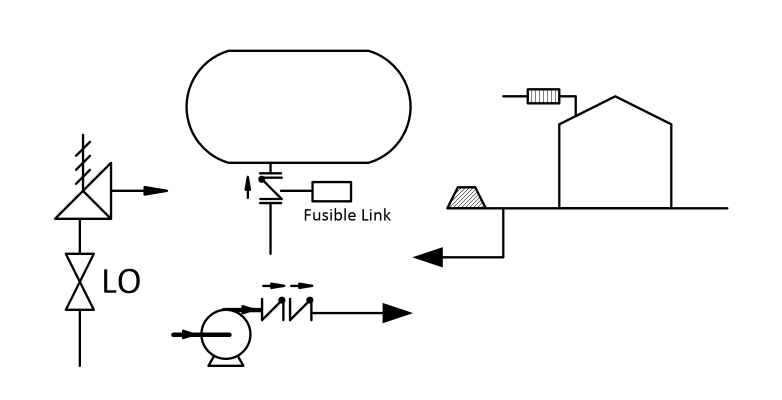
Excess Flow Valves

Excess flow valves are typically installed to prevent the uncontrolled flow of hazardous material from a vessel to the environment should an external failure occur, such as failure of light ends pump seals or other loss of containment events involving equipment downstream of the process vessel. They are also found in transportation applications such as truck loading racks or in pipelines.

In regulated industries such as transportation and pipelines, excess flow valves typically have high visibility and usually get tested and maintained. However, in process applications, this isn’t necessarily the case. Process excess flow valves are often installed at the outlet of a process vessel and are of a design that uses a check valve installed in a reversed position. The check valve is held open by a mechanical linkage that is released by either a fusible link that melts when exposed to a fire or a solenoid valve that releases the linkage, and sometime both.

Once installed, these valves appear remarkably common. They look like most any other check valve and often get ignored and sometimes forgotten about. I recall being in an older process unit on other business when I just happened to notice a couple of wires hanging from an open conduit. In itself this was a big issue as if those wires were energized an ignition event could occur. So, I started to look around and found an old, solenoid operated excess flow valve nearby that was missing its wires. Worse yet, the excess flow valve hadn’t operated. A bit of inspection showed that the solenoid was indeed deenergized, but the mechanical latch mechanism was severely corroded and had not allowed the valve to operate. Even more interesting was when I reported this to the Operations group, they had no idea that the excess flow valve was there. No wonder it never got looked at. The wiring disconnection appeared to be some casual modification that no one had any idea of when or who did it, or why. This incident started a hunt for other excess flow valves in the plant, which turned up another handful of issues. After decades of neglect, the excess flow valves got added to an inspection and maintenance list.  

Check Valves

In high pressure applications, such as feed pumps for hydrocrackers, other services where liquid is being pumped from a very low pressure to a very high pressure, or when a high pressure process can back flow into a low pressure process, check valves are often depended on to provide some level of overpressure protection for the low pressure system. API RP-521 recognizes this practice and recommends that credit only be taken for installations consisting of two check valves of differing designs installed in series and describes considerations that should be used in assessing potential leakage through the check valves.

The difficulty in operating these systems is that almost every pump in a process plant has at least one check valve installed in its discharge lines, so keeping track of which check valves are being credited for over pressure protection can be a challenge. It’s quite easy to lose track of these valves and not give them the routine inspection and leak testing required for those services which are being used at IPLs or to reduce the low-pressure relief system requirements. The check valves that are used for these purposes are usually high-pressure designs (2500 or 1500 pound class) and are difficult to maintain due to weight and sometimes being installed with welded ends. At the same time, the hazards of a failed check valve service are quite high, as high-pressure backflow will generally result in the rapid unscheduled disassembly of the low-pressure equipment.

Flame Arrestors

Flame arrestors are static device, usually consisting of some form of metal mesh or similar convoluted flow passages at the location where a tank or other vessel is vented to atmosphere. Flame arrestors are designed to prevent flame propagation from the vent outlet back into the tank or vessel, usually by cooling an external flame and reducing the flame propagation velocity.

Flame arrestors are passive devices and may remain in place for many years without any attention. This often results in the functionality being compromised due to build up of dirt, insect nests, corrosion or other degradation. Flame arrestor design is also based upon a very specific set of conditions such as the flammable material contained in the tank and environmental conditions. It is not that difficult to compromise or plug up a flame arrestor, and there are reports of them failing to function when needed or being found in an inoperable condition when inspections were eventually performed.

Block Valve Lock Systems

In some process designs, safe operation of the process is depended upon block valves installed for maintenance, startup or shutdown operations being kept in specific positions, either opened or closed. For example, pressure relief system designs are often dependent upon block valve installed under pressure relief devices being kept open at all times, or other block valves required to isolate parallel equipment being kept open whenever process fluids are in the system.

Often block valve lock systems are manually managed with only manual monitoring. The physical “lock” varies with the operations, ranging from simple aluminum car seals such as those used on rail cars or truck doors, to new plastic designs, to designs that used metal cables or chains with physical locks. In some cases, an organization will attempt to not use physical barriers and rely only upon hanging warning tags on valves.  

Use of block valve lock systems requires that there be a robust administration system whereby the status of all locked open or closed valves are continuously kept and logged, and that procedures to follow when removing or installing a block valve lock/seal and changing of the valve positions are clearly specified and followed. If locking systems are used, an additional layer of tracking of keys is also required.

For a process plant of any size, there may be a large number of block valves that are designated as CSO, CSC, LO, LC etc. (Car Seal Open, Car Seal Closed, Locked Open, Locked Closed). Administration of these valve seals or locks is no small task and more than a few units have failed surveys of their valve lock systems.

Captive Key Systems

Captive key systems are a step above the use of simple valve seals and locks. In most cases, captive key systems are used in applications where a number of valves or other equipment must have their status changed in a specific order. In these systems, the valves or other operating equipment are provided with a mechanism that requires that a key be used to unlock the valve or system for operation. The mechanism captures the initiating key when the operation is performed and releases another key that is used to operate the next valve or system in the sequence. The system has multiple keys, all of which are different. When using a captive key system, the operator starts with an initiating key that is used to operate the first device in the chain. Keys are trapped and released in sequence, with the final device releasing a key that then is stored in a safe location. When the sequence is to be reversed, the operator starts with the final key and the sequence is reversed.

Captive key systems are often used to assure that equipment is safely isolated for entry or maintenance, such as in high voltage electrical systems, or in systems that require a large number of sequential valve movements to isolate equipment such as a spare reactor. The challenges of ownership are administration of the starting and ending keys, so they do not get lost and keeping the various locking mechanisms clean and operable. The use of these systems is often very infrequent and it’s not difficult to lose track of keys or find that the locking mechanisms aren’t working when needed.

Conclusions

Non-Instrumented IPLs have process safety roles that are every bit as important as Instrumented IPLs. However, as they are often passive design features and may be so similar to other equipment, they often fall out of view and fail due to age, neglect or modifications. It is of critical importance that these Non-Instrumented IPLs are clearly documented and that their process safety functions are clearly communicated to Operations and Maintenance personnel so they can be taken into account during Management of Change activities. A system that manages only Instrumented IPLs and does not allow management of Non-Instrumented IPLs is incomplete and can be an obstacle to effective IPL and Process Safety Management.


Rick Stanley has over 40 years’ experience in Process Control Systems and Process Safety Systems with 32 years spent at ARCO and BP in execution of major projects, corporate standards and plant operation and maintenance. Since retiring from BP in 2011, Rick has consulted with Mangan Software Solutions (MSS) on the development and use of MSS’s SLM Safety Lifecycle Management software and has performed numerous Functional Safety Assessments for both existing and new SISs. 

Rick has a BS in Chemical Engineering from the University of California, Santa Barbara and is a registered Professional Control Systems Engineer in California and Colorado. Rick has served as a member and chairman of both the API Subcommittee for Pressure Relieving Systems and the API Subcommittee for Instrumentation and Control Systems. 


Digital Transformation of Control and Safety Systems – Retired

Digital Transformation of Control and Safety Systems – Retired

The Digital Transformation of Control and Safety Systems has come a long way. They used to be simple yet were unreliable, not very robust, or died from neglect.  In the past, the term Safety System generally wasn’t used very much, rather you would see terms such as ESD and Interlock. The technologies used in the past were often process connected switches and relays that were difficult to monitor, troubleshoot, and maintain. Field instrumentation used 3-15 psig air or 4-20 ma signals. Things have changed since then. They have become more effective yet with that, a lot more complicated as well. 

The Digital Transformation of Control and Safety Systems has come a long way. They used to be simple yet were unreliable, not very robust, or died from neglect.  In the past, the term Safety System generally wasn’t used very much, rather you would see terms such as ESD and Interlock. The technologies used in the past were often process connected switches and relays that were difficult to monitor, troubleshoot, and maintain. Field instrumentation used 3-15 psig air or 4-20 ma signals. Things have changed since then. They have become more effective yet with that, a lot more complicated as well. 

As control systems, safety systems, and field instrumentation were digitized, the amount of data a user has to specify and manage grew by orders of magnitude. Things that were defined by hardware design, that were generally unchangeable after components were specified, became functions of software and user configuration data which could be changed with relatively little effort.  This caused the management of changes, software revisions, and configuration data to become a major part of ownership. 

The problem is that the market is dominated by proprietary systems that apply only to manufacturers line of products, so the user is required to have multiple software packages to support the wide variety of instrumentation, control systems, safety systems and maintenance management support systems that exist in any of today’s process plants. Here’s an overview of the evolution and landscape of these systems and the relative chaos that still exists. 

What are industry leaders like Shell doing to digitally transform their process safety lifecycle?

Process Plant Control and Safety System Software Overview


 Field Instrumentation 

Back in the early 1980’s an operating company was involved in the first round of process control system upgrades to the first generation of DCS that were available. There were projects for field testing prototypes of a new digital transmitter major manufacturers. The transmitters that were being tested were similar to the 4-20 ma transmitters, but the digital circuity that replaced the old analog circuitry was programmed by a bulky handheld communicator. It took about 10 parameters to set up the transmitter. 

Now you can’t buy anything other than a digital transmitter, and instead of a few parameters available, there are dozens. Digital valve controllers have also become common and the number of parameters available number in the hundreds. Device types with digital operation have also exploded, including adoption of wireless and IOT devices. The functionality and reliability of these devices far exceed those of their prior analog circuit-based relatives. The only cost is that someone has to manage all of that data. A binder full of instrument data sheets just doesn’t work anymore. 

Field Instrumentation Management Systems 

When digital field instrumentation was first introduced the only means of managing configuration data for each device was through a handheld communications device, and the configuration data resided only on the device. This was simple enough when the parameters mirrored the settings on non-smart devices. However, these devices got more sophisticated and the variety of devices available grew. Management of their configuration data became more demanding and the need for tools for management of that data became fairly obvious.

The market responded with a variety of Asset Management applications and extended functionality from basic configuration date management to include calibration and testing records and device performance monitoring.  The systems were great, but there was major problem in that each manufacturer had packages that were proprietary to their lines of instrumentation.

There have been attempts to standardize instrument Asset Management, such as the efforts of the FTD group, but to date most users have gravitated towards specific manufacturer software based upon their Enterprise or Site standard suppliers. This leaves a lot of holes when devices from other suppliers are used, especially niche devices or exceptionally complex instruments, such as analyzers are involved. Most users end up with one package for the bulk of their instrumentation and then a mix of other packages to address the outliers, or no management system for some devices. Unfortunately, manufacturers aren’t really interested in one standard. 

Communications Systems 

As digital instrumentation developed, the data available was still constrained by a single process variable transmitted over the traditional 4-20 ma circuit. The led to development of digital communications methods that would transmit considerable device operation and health data over top of, or in replacement of, the 4-20 ma PV signal. The first of these was the HART protocol developed by one manufacturer but released to the industry as an open protocol. However, other manufacturers developed their own protocols that were incompatible with HART. As with Asset Management software, the market is divided up into competing proprietary offerings and a User has to make choices on what to use.

 In the 1990’s, in an attempt to standardize something, the Fieldbus Foundation was established to define interoperable protocols. Maneuvering for competitive advantage led some companies to establish their own consortiums such as Profibus and World FIP that used their own protocols. The field instrument communications world has settled on a few competing and incompatible systems. Today a user basically has to make a choice between HART, Fieldbus, Profibus and DeviceNet, and then use the appropriate, often proprietary, support software and hardware. 

Distributed Control Systems and PLC’s 

1980 is back when programming devices required customized hardware. The PLC had its own suitcase sized computer that could only be used for the PLC. Again, data was reasonably manageable, but a crude by today’s standards. 

Over the years the power of the modules has evolved from the original designs that could handle 8 functions, period, to modules that can operate all or most of a process plant. The industry came up with a new term, ICSS for Integrated. Control and Safety System to describe DCS’s that had been expanded to include PLC functions as well as Safety Instrumented Systems. 

The data involved in these systems has likewise exploded as has the tools and procedures for managing that data.  The manufacturers of the DCS, PLC and SIS systems have entire sub-businesses devoted to the management of the data associated with their systems. 

As with other systems software the available applications are usually proprietary to specific manufacturers. Packages that started out as simpler (relatively speaking) configuration management software were extended to include additional functions such as alarm management, loop turning and optimization, and varying degrees of integration with field device Asset Management Systems. 

Safety Instrumented Systems 

Safety Instrumented System logic solvers were introduced in the earl 1980’s, first as rather expensive and difficult to own stand-alone systems. The SIS’s evolved and became more economic. While there still are stand along SIS available, some of the DCS manufacturers have moved to offering Integrated Control and Safety Systems (ICSS) in which SIS hardware and software for Basic Process Control (BPCS), SIS and higher-level functions such as Historians and Advanced Control applications are offered within integrated product lines.

 As with all of the other aspects of support software, the packages available for configuration and data management for SIS hardware and software is proprietary to the SIS manufacturers. 

Operation and Maintenance Systems 

The generalized Operation and Maintenance Systems that most organizations use to manage their maintenance organizations exist and have been well developed for what they do. Typically, these packages are focused on management of work orders, labor and warehouse inventory management and aren’t at all suitable for management of control and safety systems.

 Most of the currently available packages started out as offerings by smaller companies but have gotten sucked up into large corporations that have focused on extending of what were plant level applications into full Enterprise Management Systems that keep the accountants and bean counters happy, but make life miserable for the line operations, maintenance and engineering personnel. I recall attending an advanced control conference in which Tom Peters (In Search of Excellence) was the keynote speaker. He had a sub-text in his presentation that he hated EMS, especially SAP. His mantra was “SAP is for saps”, which was received by much head nodding in the audience of practicing engineers. 

Some of the Operations and Maintenance Systems have attempted to add bolt on functionality, but in my view, they are all failures. As described above, the management tools for control and safety systems are fragmented and proprietary and attempting to integrate them into generalized Operation and Maintenance Systems just doesn’t work. These systems are best left to the money guys who don’t really care about control and safety systems (except when they don’t work). 

Process Safety System Data and Documentation 

The support and management software for SIS’s address only the nuts and bolts about programming and maintaining SIS hardware. They have no, or highly limited functionality for managing the overall Safety Life Cycle from initial hazard identification through testing and maintaining of protective functions such as SIFs and other Independent Protection Layers (IPLs). Some of the Operation and Maintenance System suppliers have attempted to bolt on some version of Process Safety Management functionality, but I have yet to see one that was any good. In the last decade a few engineering organizations have released various versions of software that integrate the overall Safety Lifecycle phases. The approach and quality of these packages varies. I’m biased and think that Mangan Software Solutions’ SLM package is the best of the available selections. However, The ARC Advisory Group also agrees.

 Digital Transformation of Control and Safety Systems

Click Here To Learn More

 Conclusions  

The Digital Transformation of Control and Safety Systems has resulted in far more powerful and reliable systems than their analog and discrete component predecessors. However, the software required to support and manage these systems is balkanized mixed of separate, proprietary and incompatible software packages, each of which has a narrow scope of functionality. A typical plant user is forced to support multiple packages based upon the control and safety systems that are installed in their facilities. The selection of those systems needs to consider the support requirements for those systems, and once selected it is extremely difficult to consider alternatives as it usually requires a complete set of parallel support software which will carry its own set of plant support requirements. Typically, a facility will require a variety of applications which include: 

  • Field device support software and handheld communicators
  • Field device Asset Management Software, typically multiple packages if the User uses multiple suppliers
  • DCS/BPCS/PLC/ICSS support software for configuration, alarm management and optimization functions as used by the Site. If a Site has multiple suppliers, then multiple parallel packages are required
  • SIS support software for configuration and software management if not integrated with and ICSS software package. If a Site has multiple suppliers, then multiple parallel packages are required
  • Operations and Maintenance Management packages – selected by others and not within the control of personnel responsible for Process Control and Safety Systems.
  • Safety Lifecycle Management Software – preferably an integrated package that includes Hazard Analysis, Safety Function and System design and Safety Function testing, event data collection and performance analysis and management functions.

 So choose wisely.  

Rick Stanley has over 40 years’ experience in Process Control Systems and Process Safety Systems with 32 years spent at ARCO and BP in execution of major projects, corporate standards and plant operation and maintenance. Since retiring from BP in 2011, Rick has consulted with Mangan Software Solutions (MSS) on the development and use of MSS’s SLM Safety Lifecycle Management software and has performed numerous Functional Safety Assessments for both existing and new SISs. 

Rick has a BS in Chemical Engineering from the University of California, Santa Barbara and is a registered Professional Control Systems Engineer in California and Colorado. Rick has served as a member and chairman of both the API Subcommittee for Pressure Relieving Systems and the API Subcommittee for Instrumentation and Control Systems. 

Capital Project Execution Case Study

capital project case study

This Capital Project Execution Case Study highlights the successful outcome of a recent proof of concept using Safety Lifecycle Manager (SLM).

Please complete the form below and you will be redirected you to your download.

11 + 15 =

Mangan Software Solutions Named #1 Global Supplier by ARC Advisory Group

FOR IMMEDIATE RELEASE                      

Contact: Michelle Smith      

Mangan Software Solutions  

msmith@manganinc.com 

 281.402.2641 ext. 514  

 mangansoftware.com  

 Houston, TX // January 16,2020 


Mangan Software Solutions (MSS), the leading independent supplier of enterprise wide safety lifecycle management software was named the #1 Global Supplier in the ARC Advisory Group’s 2019 Process Safety Lifecycle Management Global Market Report for its award-winning flagship product, Safety Lifecycle Manager (SLM ®).  Additionally, SLM® is mentioned as commanding over half the market for Enterprise solutions in the Refining, and Oil & Gas sectors.  The report provides an in-depth market share analysis as well as future recommendations for suppliers and buyers based on global market data and trends.  

“Safety regulations and standards continue to drive companies to seek ways to ensure compliance with limited resources.  End users across the process industries today are attempting to address the sometimes-confusing array of safety regulations and standards. Custom spreadsheets fail to adequately meet the needs of today’s enterprises. Holistic solutions like Mangan Software’s Safety Lifecycle Manager help users easily and properly maintain their process safety systems to ensure adequate protection in an auditable manner,” noted Mark Sen Gupta, Director of Research at ARC Advisory Group.  

SLM ® is a proven, innovative, easy-to-use cloud-based platform, intricately designed to solve the toughest Process Safety Lifecycle Management challenges.  As one of the most widely used, comprehensive platforms, SLM ® transforms process safety information into process safety intelligence, providing organizations unprecedented visibility and advanced analytics.  SLM ® continues to set the standard through innovation, quality, and delivering results that companies can trust.   

SLM ® PROVIDES:  

  • Cleaner hand-over of process safety information to operations during capital projects, digital project execution and seamless handover, data-centric. 
  • Improved efficiency and risk transparency, by eliminating disparate sources of data and reporting systems.  Single Source of Truth. 
  • An integrated digital backbone for sustainable, scalable transformation. 
  • Standardized, fit-for-purpose platform that vastly streamlines lifecycle and asset integrity activities and costs. 
  • Performance Monitoring: Evaluate the performance and adequacy of safeguards design/engineering to operations, and ensuring protection barriers are managed effectively and efficiently  
  • Access to relevant evergreen information instantly, from the highest level KPI’s down to the instrument, allowing users to make critical safety decisions with confidence.  

“We at Mangan Software Solutions, are honored to have received such distinction and recognition by ARC Advisory Group,” says Ronak Patel, Vice President, Sales & Marketing.  “Our mission has always been to deliver value through innovation. Using our latest cloud technology platform, SLM continues to digitally transform traditional Process Safety Lifecycle Management practices and deliver sustainable ROI for our clients.”   

MSS will showcase SLM and its process safety lifecycle management capabilities at the 24th Annual ARC Industry Forum in Orlando on February 3-6, 2020, in Booth #40. 

 Click here to see event details  

ABOUT Mangan Software Solutions: MSS is a wholly owned subsidiary of Mangan, Inc. that leverages technology and software services to standardize and automate business processes for the energy industry. Headquartered in Houston, with offices in Atlanta and London, MSS’ engineers and developers are experts in the fields of Safety Lifecycle Management and Safety Instrumented Systems and deploy their industry best practice flagship SLM platform suite to industries that require reliable high-performance automation solutions.   


 For further information, visit www.mangansoftware.com