I Like Logic Diagrams

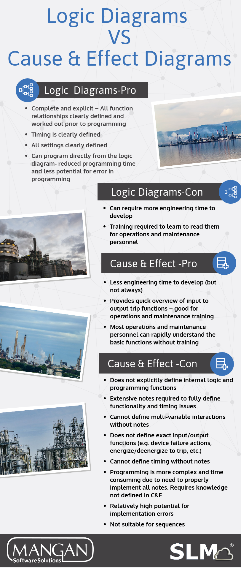
I like logic diagrams, although I’m often in the minority, to do the detailed design of a Safety Instrumented Function (SIF). Others believe that Cause and Effect (C&E) Diagrams are all that is needed. My view is that C&E’s are an effective overview tool when it comes to familiarizing people that aren’t part of the design team with a SIF’s function. However, when it comes to clearly and unambiguously defining how a SIF, or any other logic function works, I find the logic diagram to be the best tool.
C&E’s just are not very good in conveying stuff like timing or sequencing, rather they are quite confusing. C&E’s are good at saying if an input condition exists, this is the output condition. But more complex things such as timing, permissives and other things that usually exist can’t be readily defined in a C&E. Suddenly you are trying to figure out what Notes 6, 12, and 19 actually mean. Users programming from C&E’s, particularly for larger systems can easily make mistakes or misinterpret the intent. I find myself to be quite capable of misinterpreting all those notes.
I like logic diagrams because on the other hand, when done well, they are easy to interpret. The diagram symbols like those identified in a standard such as ISA 5.2 allow the user to clearly define almost everything you need. You can clearly and precisely cover set points, time delays, and complex relationships etc. Personally, I’ve used an amended version where input and outputs get more directly defined as power sources, dead bands for switches, whether the logic operates on an open or closed switch, or energizes or de-energizes a solenoid valve, etc.
Logic diagrams also can become a one to one road map for the Safety Instrumented System (SIS) programming. Most SIS programming languages have a function block option. This makes things a whole lot easier and saves a lot of time in programming, quality checking and field testing. It’s true that preparing a good logic diagram takes more time than putting together a C&E, but it’s my belief that you get your money back and then some just in simplicity and reduced errors. It’s simple to put a note on a C&E that someone might easily misunderstand, but in a logic diagram you have to sweat the details up front and not pass it on for a programmer to figure out (and everyone thereafter).
I think that logic diagrams are an investment. They take time to prepare yet start paying back at the time of programming. The real payout comes at the time of pre-startup validation. With well-reviewed logic diagrams, the potential errors in programming are pretty much beat out of the system by the time you get to checkout, loop testing, and validation. Well checked and tested systems can radically reduce startup time.
An example of what a logic diagram looks like:
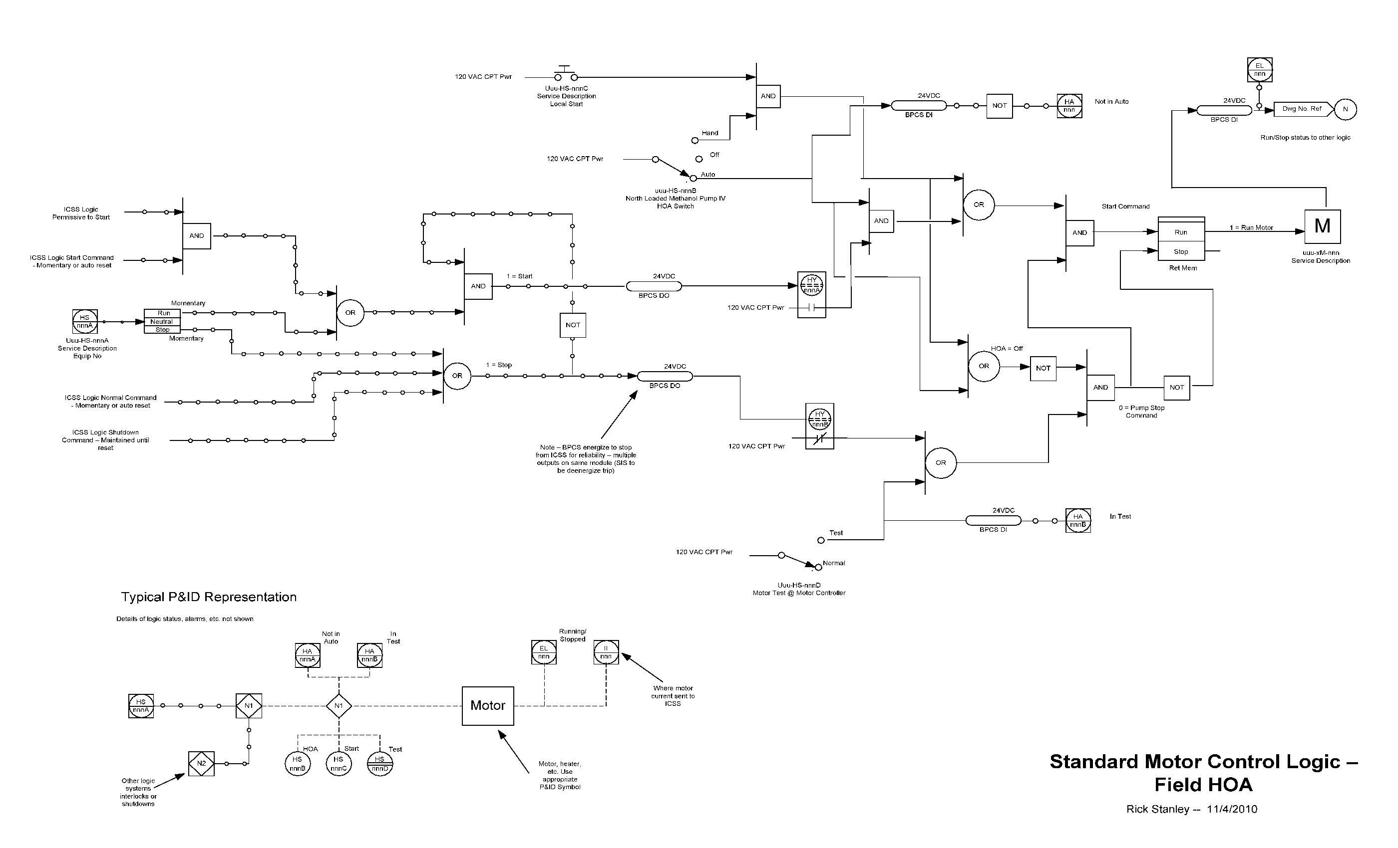
A case study I cite is a process unit for which I was the lead control systems engineer. The process required over 100 distinct Interlock, sequence and SIFs as well as required over 400 logic diagrams to represent. We spent a ton of time developing the logic diagrams and a bunch more putting together test procedures and executing them. We taught the Operators to read the logic diagrams, and during the first 6 months of operation, there was always one set or another open on a desk.
It took a lot of effort, and had real costs, when it was all said and done, we only had two logic glitches during startup (one of those was an unauthorized logic change made by a contract engineer at the last minute). The net result was that we were up and making on spec product in the first week of operation. The licensor’s startup engineers were amazed. Their feedback was that they always experienced that there would be 6 to 8 weeks of logic debugging before reliable production could be established. The extra 5 weeks of production paid for all of time we spent on logic diagrams and testing, many times over. That’s why I like logic diagrams.
Rick Stanley has over 40 years’ experience in Process Control Systems and Process Safety Systems with 32 years spent at ARCO and BP in execution of major projects, corporate standards and plant operation and maintenance. Since retiring from BP in 2011, Rick formed his company, Tehama Control Systems Consulting Services, and has consulted with Mangan Software Solutions (MSS) on the development and use of MSS’s Safety Lifecycle Management software.
Rick has a BS in Chemical Engineering from the University of California, Santa Barbara and is a registered Professional Control Systems Engineer in California and Colorado. Rick has served as a member and chairman of both the API Subcommittee for Pressure Relieving Systems and the API Subcommittee on Instrumentation and Control Systems.