Process Safety Data for Pressure Relief Systems

Process Safety Data for Pressure Relief Systems
Pressure Relief Systems have been around a long time, but the documentation of their Process Safety Data has a pretty tortured past. Due to the relatively long history, dating back to the early boilers in locomotives and steamboats, there are lots of regulations that grew a bit haphazardly in response to early incidents.
Most States in the US have regulations for pressure relief devices, however those regulations are all over the place in defining Process Safety Data requirements. Some are focused on Relief Device Inspection, Testing and Repair while others attempt to address other aspects of Pressure Relief System Process Safety Data. Some states hardly address Pressure Relief Systems, while others have provisions that focus on single applications in great detail. Some cities have their own rules independent of State rules.
The National Board of Boiler and Pressure Vessel Inspections has published a summary of the various US and Canada regulations. These regulations are inconsistent from jurisdiction to jurisdiction, are usually incomplete, and often are well out of date.
Click here to review The National Board Synopsis
While most jurisdictions address basics such as identifying ASME Section I and Section VIII Code (often an obsolete, dated version and not the current version), they generally address only a few of the things an owner should be doing to properly administrate the design, installation, operation and maintenance of Pressure Relief Systems. They can focus on the oddest aspects of relief systems and not address other critical requirements. This can result in organizations deciding they only have to comply with a few requirements, when really, they should be doing much more.
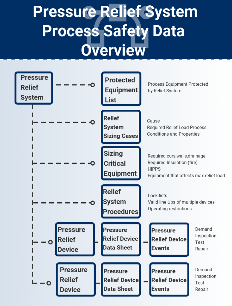
The overall structure of a robust Pressure Relief System Process Safety Data program is illustrated in the figure below. Each of these items is described in the sections below.
Pressure Relief System Definition
The first consideration in maintaining Process Safety Information is to have a definition of the scope of a Pressure Relief System. A single Pressure Relief System consists of one or more pressure relief devices, the equipment and piping that the Pressure Relief System protects, and any other relevant equipment such as block valves or supplemental devices. Some jurisdictions require this to be clearly documented but others do not specifically address this requirement.
The Process Safety Information for a Pressure Relief System should include material that clearly defines the scope and boundaries of each System. This may take the form of a sketch that shows all relevant equipment, piping and pressure relief devices or a list that contains the same information.
However, an issue with sketches or lists is that it can be difficult to verify that all equipment in a facility is adequately protected from over pressure. The sketches and lists can effectively document what is protected, but it is a much more difficult task to find what may have been left out. Ideally, a database that allows linking of Pressure Relief System definition to a complete equipment data base should be used. Query of this database can rapidly identify equipment that may not have over pressure protection.
Process Sizing Basis
When a Pressure Relief System is designed, a large number of potential Pressure Relief System sizing scenarios, usually based upon the descriptions contained in API RP-521, are evaluated by a Process Engineering group. The case that requires the largest pressure relieving device sizes is recorded as the sizing case. This is the process data that makes it to the pressure relief device data sheets. The full process analysis often then goes into a box that gets sent to the owner with all of the other design documentation. Often this box goes into long term storage somewhere and is seldom seen again.
Processing facilities are dynamic things, and modifications and improvements often affect the required pressure relief capacity. If the original Relief System sizing calculations are stored in an inaccessible box, every change requires a full re-evaluation of the Pressure Relief System from scratch. This is something that becomes prohibitive and the required evaluations often don’t get done, are highly inefficient, or are inconsistent with the initial evaluations.
Pressure Relief System sizing evaluations and calculations for all of the pressure relief causes should be retained in records that are readily available when the Pressure Relief System needs to be re-evaluated. These can take the form of paper records or scanned records stored digitally, but the key point is that a complete, progressive and up to date set of Pressure Relief System sizing evaluations and calculations needs to be kept in a format and location that allows for efficient recall, review and update.
Relief Device Specifications
The physical specifications for Pressure Relief Devices are typically contained on data sheets used to purchase the devices. These sheets contain physical requirements such as manufacturer, model number, materials of construction, body and process connection ratings, required relief area and the process conditions for the relief device sizing case. Often these data sheets are the only Pressure Relief Process Safety data that is readily available to a Site’s staff and are often erroneously considered to be full documentation.
What is often not appreciated, is that the information contained on a Pressure Relief Device data sheet is only a subset of the full information required to own and maintain the Pressure Relief Devices. These data sheets are used as tool for procurement and contain only the information needed to procure a specific device. They are an integral part of the Relief System Process Safety data, but only a small part. In addition to the Pressure Relief System evaluation records described above, a complete set of manufacturer’s manuals need to be available to identify key parts and dimension tolerances.
Relief Device Installation
The proper functioning of Pressure Relief Devices requires that they be properly installed, and the systems around them such as inlet and output piping, block valves and other support devices be properly designed. For example:
Section VIII spring opposed pressure relief valves have rather narrow requirements for the dynamic inlet losses (the 3% rule) and have similar requirements for both static and dynamic back pressures. Inlet and outlet block valves also have size and design restrictions, such as requirements that all block valves be at least full ported valves that do not restrict flow to the pressure relief device. There are also specific limitations of the static and dynamic piping loads that can be imposed upon pressure relief device bodies.
The Process Safety Data for a Pressure Relief System should include full installation specifications and support calculations. Support calculations should include inlet and output pressure losses and imposed back pressures and piping load calculations, including both relieving and non-relieving conditions. These calculations should be kept in a readily accessible format and locations similar to the requirements for Process Sizing evaluations and calculations.
Associated Relief System Equipment
The design of a pressure relief system dependent upon the capacity of other equipment requires that certain equipment be in service at all times the pressure relief system may have a demand placed upon it. This equipment and other functions must be identified. Some examples are:
- The capacity of process equipment such as fired heater duties, pump impeller sizes, etc.
- Relief systems subject to fire cases require that the assumed vessel insulation is in place and of a design that can withstand external fire
- HIPPS or other equipment installed to reduce the required relief load are in service
- Block valve locks and required block valve positions
Pressure Relief System Procedures
Any Pressure Relief System Process Safety Data system includes the procedures required to safely operate the systems. This includes items such as:
- Safe Operating Limits within which the Pressure Relief System is properly sized
- Lock Lists and Lock/Car Seal status
- Permissible line-ups for system with multiple relief devices and installed spares
- Other operating restrictions required to safety operate the Pressure Relief System
Relief Device Inspection, Testing and Maintenance
Almost all jurisdictions require that Pressure Relief Devices be inspected, tested and repaired at regular intervals, and that the results of these activities be kept in a progressive record. The National Board of Boiler and Pressure Vessel Inspectors VR stamp program defines a set of minimum qualifications, procedures and documentation for the inspection, testing and repair of pressure relief devices. Some jurisdictions make it mandatory that any organization doing inspection, testing and repair of pressure relief devices hold a VR stamp. Other jurisdictions may have other requirements. In any event, a pressure relief system management program should include a robust device inspection, testing and repair program including complete documentation of all events associated with the Pressure Relief System and its devices.
Management of Change
All Pressure Relief Systems are subject to Management of Change procedures whenever modifications are made to process equipment or to the Relief System components. Often de-bottlenecking projects will increase equipment capacity, which then can impact the sizing criteria for the Pressure Relief Systems. Modifications to the pressure relief devices can also affect pressure relief system performance or affect the physical installation of the devices and their associated piping and equipment. Even apparently small changes such as modifying a pump impeller or vessel insulation can result in an improperly sized Pressure Relief System. Therefore, it is imperative that whenever a change is made to a process that its effect on Pressure Relief System design be fully evaluated and the required changes to the Pressure Relief System also be implemented and documented.
Rick Stanley has over 40 years’ experience in Process Control Systems and Process Safety Systems with 32 years spent at ARCO and BP in execution of major projects, corporate standards and plant operation and maintenance. Since retiring from BP in 2011, Rick formed his company, Tehama Control Systems Consulting Services, and has consulted with Mangan Software Solutions (MSS) on the development and use of MSS’s Safety Lifecycle Management software.
Rick has a BS in Chemical Engineering from the University of California, Santa Barbara and is a registered Professional Control Systems Engineer in California and Colorado. Rick has served as a member and chairman of both the API Subcommittee for Pressure Relieving Systems and the API Subcommittee on Instrumentation and Control Systems.